multi function shield examples
This shield got my attention as it looked like a nice beginners learning type shield with which you could get up and running with an Arduino
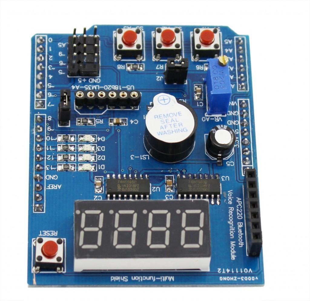
Here is a picture of the board, a few code examples are available later on in the article.
 http://arduinolearning.com/wp-content/uploads/2014/12/multi-function-shield-300x290.jpg 300w, http://arduinolearning.com/wp-content/uploads/2014/12/multi-function-shield-150x145.jpg 150w, http://arduinolearning.com/wp-content/uploads/2014/12/multi-function-shield-400x387.jpg 400w" sizes="(max-width: 1024px) 100vw, 1024px" style="border: 0px none !important; margin: 5px 0px; padding: 0px !important; max-width: 96%; width: auto; height: auto;">
multi function shield
Features
4 digit 7-segment LED display module driven by two serial 74HC595’s
4 LED’s
10K potentiometer
3 x push buttons
Piezo buzzer
DS18B20 temperature sensor interface (not included)
Infrared receiver interface
Serial interface header for connection to serial modules
Code Examples
********************************************************************
Blinking LED
|
1
2
3
4
5
6
7
8
9
10
11
12
13
|
int led = 13;void setup(){// initialize the digital pin as an output.pinMode(led, OUTPUT);}void loop(){digitalWrite(led, HIGH);delay(1000);digitalWrite(led, LOW);delay(1000);} |
********************************************************************
All LEDS blinking
|
1
2
3
4
5
6
7
8
9
10
11
12
13
14
15
16
17
18
19
20
21
22
23
24
25
|
int led1 = 13;int led2 = 12;int led3 = 11;int led4 = 10;void setup(){// initialize the digital pin as an output.pinMode(led1, OUTPUT);pinMode(led2, OUTPUT);pinMode(led3, OUTPUT);pinMode(led4, OUTPUT);}void loop(){digitalWrite(led1, HIGH);digitalWrite(led2, HIGH);digitalWrite(led3, HIGH);digitalWrite(led4, HIGH);delay(1000);digitalWrite(led1, LOW);digitalWrite(led2, LOW);digitalWrite(led3, LOW);digitalWrite(led4, LOW);delay(1000);} |
********************************************************************
Switches example
|
1
2
3
4
5
6
7
8
9
10
11
12
13
14
15
16
17
18
19
20
21
22
23
24
25
26
27
28
29
|
const byte LED[] = {13,12,11,10};#define BUTTON1 A1#define BUTTON2 A2void setup(){// initialize the digital pin as an output./* Set each pin to outputs */pinMode(LED[0], OUTPUT);pinMode(LED[1], OUTPUT);pinMode(LED[2], OUTPUT);pinMode(LED[3], OUTPUT);}void loop(){if(!digitalRead(BUTTON1)){digitalWrite(LED[0], HIGH);digitalWrite(LED[1], HIGH);digitalWrite(LED[2], HIGH);digitalWrite(LED[3], HIGH);}if(!digitalRead(BUTTON2)){digitalWrite(LED[0], LOW);digitalWrite(LED[1], LOW);digitalWrite(LED[2], LOW);digitalWrite(LED[3], LOW);}} |
********************************************************************
Potentiometer 1
|
1
2
3
4
5
6
7
8
9
10
11
12
13
|
#define Pot1 0void setup(){Serial.begin(9600);}/* Main Program */void loop(){Serial.print(“Potentiometer reading: “);Serial.println(analogRead(Pot1));/* Wait 0.5 seconds before reading again */delay(500);} |
********************************************************************
Pot and led
|
1
2
3
4
5
6
7
8
9
10
11
12
13
14
15
16
17
18
19
20
21
22
23
24
25
26
27
28
29
30
31
32
33
34
35
36
37
38
39
|
const byte LED[] = {13,12,11,10};#define Pot1 0void setup(){Serial.begin(9600);// initialize the digital pin as an output./* Set each pin to outputs */pinMode(LED[0], OUTPUT);pinMode(LED[1], OUTPUT);pinMode(LED[2], OUTPUT);pinMode(LED[3], OUTPUT);}/* Main Program */void loop(){int PotValue;//Serial.print(“Potentiometer reading: “);PotValue = analogRead(Pot1);/* Wait 0.5 seconds before reading again */if(PotValue < 400){digitalWrite(LED[0], LOW);digitalWrite(LED[1], LOW);digitalWrite(LED[2], LOW);digitalWrite(LED[3], LOW);Serial.print(“Potentiometer: “);Serial.println(PotValue);}else{digitalWrite(LED[0], HIGH);digitalWrite(LED[1], HIGH);digitalWrite(LED[2], HIGH);digitalWrite(LED[3], HIGH);Serial.print(“Potentiometer: “);Serial.println(PotValue);}delay(500);} |
********************************************************************
segment display
|
1
2
3
4
5
6
7
8
9
10
11
12
13
14
15
16
17
18
19
20
21
22
23
24
25
26
27
28
29
30
31
32
|
/* Define shift register pins used for seven segment display */#define LATCH_DIO 4#define CLK_DIO 7#define DATA_DIO 8/* Segment byte maps for numbers 0 to 9 */const byte SEGMENT_MAP[] = {0xC0,0xF9,0xA4,0xB0,0x99,0x92,0x82,0xF8,0X80,0X90};/* Byte maps to select digit 1 to 4 */const byte SEGMENT_SELECT[] = {0xF1,0xF2,0xF4,0xF8};void setup (){/* Set DIO pins to outputs */pinMode(LATCH_DIO,OUTPUT);pinMode(CLK_DIO,OUTPUT);pinMode(DATA_DIO,OUTPUT);}/* Main program */void loop(){/* Update the display with the current counter value */WriteNumberToSegment(0 , 0);WriteNumberToSegment(1 , 1);WriteNumberToSegment(2 , 2);WriteNumberToSegment(3 , 3);}/* Write a decimal number between 0 and 9 to one of the 4 digits of the display */void WriteNumberToSegment(byte Segment, byte Value){digitalWrite(LATCH_DIO,LOW);shiftOut(DATA_DIO, CLK_DIO, MSBFIRST, SEGMENT_MAP[Value]);shiftOut(DATA_DIO, CLK_DIO, MSBFIRST, SEGMENT_SELECT[Segment] );digitalWrite(LATCH_DIO,HIGH);} |
********************************************************************
Read pot and display value on display
|
1
2
3
4
5
6
7
8
9
10
11
12
13
14
15
16
17
18
19
20
21
22
23
24
25
26
27
28
29
30
31
32
33
34
35
36
37
38
|
/* Define shift register pins used for seven segment display */#define LATCH_DIO 4#define CLK_DIO 7#define DATA_DIO 8#define Pot1 0/* Segment byte maps for numbers 0 to 9 */const byte SEGMENT_MAP[] = {0xC0,0xF9,0xA4,0xB0,0x99,0x92,0x82,0xF8,0X80,0X90};/* Byte maps to select digit 1 to 4 */const byte SEGMENT_SELECT[] = {0xF1,0xF2,0xF4,0xF8};void setup (){Serial.begin(9600);/* Set DIO pins to outputs */pinMode(LATCH_DIO,OUTPUT);pinMode(CLK_DIO,OUTPUT);pinMode(DATA_DIO,OUTPUT);}/* Main program */void loop(){int PotValue;PotValue = analogRead(Pot1);Serial.print(“Potentiometer: “);Serial.println(PotValue);/* Update the display with the current counter value */WriteNumberToSegment(0 , PotValue / 1000);WriteNumberToSegment(1 , (PotValue / 100) % 10);WriteNumberToSegment(2 , (PotValue / 10) % 10);WriteNumberToSegment(3 , PotValue % 10);}/* Write a decimal number between 0 and 9 to one of the 4 digits of the display */void WriteNumberToSegment(byte Segment, byte Value){digitalWrite(LATCH_DIO,LOW);shiftOut(DATA_DIO, CLK_DIO, MSBFIRST, SEGMENT_MAP[Value]);shiftOut(DATA_DIO, CLK_DIO, MSBFIRST, SEGMENT_SELECT[Segment] );digitalWrite(LATCH_DIO,HIGH);} |
********************************************************************
Resources
How to use FreeRTOS with Arduino – Real time operating system
In this article you will learn how to use FreeRTOS operating system with Arduino to perform specific tasks. A Real Time Operating System also known as RTOS is an operating system which is intended to fulfills the requirement of real time application. It is able to process data as comes in, typically without buffering delays. RTOS is the combination of calling predefined functions. The key factors in Real Time Operating System are minimum interrupt latency and minimum threads switching latency. The Real Time Operating System is valued more for how quickly and how predictably it responds to complete the tasks in given period of time.
There are three types of RTOS:
- Hard RTOS; bound to complete task in given deadline
- Firm RTOS; bound of deadline but if they miss the deadline it is acceptable but not in the case of Hard RTOS.
- Soft RTOS; not bound of any deadline.
Examples of RTOS:
- LynxOS
- RTLinux
- VxWorks
- FreeRTOS
- OSE
- QNX
- Windows CE
Why RTOS are required:
When we write good embedded software we do not need RTOS but when its complexity and size increases RTOS is always beneficial for the reasons listed below:
- Abstract out timing information
- Maintainability/Extensibility
- Modularity
- Cleaner interfaces
- Easier testing (in some cases)
- Code reuse
- Improved efficiency
- Idle time
- Flexible interrupt handling
- Mixed processing requirements
- Easier control over peripherals
These are the advantages of RTOS but there are also some disadvantages listed as below;
- Low Priority Tasks
- Precision of code
- Limited Tasks
- Complex Algorithms
- Device driver and interrupt signals
- Thread Priority
- Expensive
- Not easy to program
The OS used in this project is FreeRTOS. FreeRTOS is developed by Real Time Engineers Ltd. FreeRTOS is a popular Real Time Operating System kernel. FreeRTOS is open source. It is used for embedded devices which are ported in described 35 microcontrollers. It is mostly written in C but some functions are written in assembly. There are also SafeRTOS and OpenRTOS available online which are similar to FreeRTOS.
Task switching using Arduino:
In this project 3 Led indicates three tasks and one Led indicate idle state. Three tasks are labels as Task1, Task2 and Task3 respectively.
Code:
We in includes the library file on FreeRTOS
#include <Arduino_FreeRTOS.h>

void setup()

//Initialize the Serial Monitor with 9600 baud rate

{Serial.begin(9600);

Serial.println(F("In Setup function"));

//Set the digital pins 8 to 11 as output

  pinMode(8,OUTPUT);

  pinMode(9,OUTPUT);

  pinMode(10,OUTPUT);

  pinMode(11,OUTPUT);

//Create three tasks with labels Task1, Task2 and Task3 and assign the priority as 1, 2 and 3 //respectively. We also create fourth task labeled as IdelTask when the there is no task in //operation and it has the highest priority.

  xTaskCreate(MyTask1, "Task1", 100, NULL, 1, NULL);

  xTaskCreate(MyTask2, "Task2", 100, NULL, 2, NULL);

  xTaskCreate(MyTask3, "Task3", 100, NULL, 3, NULL);

  xTaskCreate(MyIdleTask, "IdleTask", 100, NULL, 0, NULL);}

//We can change the priority of task according to our desire by changing the numeric’s //between NULL texts.

void loop()

{

//There is no instruction in loop section of the code.

}

//The following function is Task1. We display the task label on Serial monitor.

static void MyTask1(void* pvParameters)

{while(1)

  { digitalWrite(8,HIGH);

    digitalWrite(9,LOW);

    digitalWrite(10,LOW);

    digitalWrite(11,LOW);

    Serial.println(F("Task1"));

    vTaskDelay(100/portTICK_PERIOD_MS);}}

//Similarly this is task 2

static void MyTask2(void* pvParameters)

{  while(1)

  { digitalWrite(8,LOW);

    digitalWrite(9,HIGH);

    digitalWrite(10,LOW);

    digitalWrite(11,LOW);

    Serial.println(F("Task2"));

    vTaskDelay(110/portTICK_PERIOD_MS);}}

//Similarly this is task 3

static void MyTask3(void* pvParameters)

{ while(1)

  { digitalWrite(8,LOW);

    digitalWrite(9,LOW);

    digitalWrite(10,HIGH);

    digitalWrite(11,LOW);

    Serial.println(F("Task3"));

    vTaskDelay(120/portTICK_PERIOD_MS);}}

//This is the idle task which has the most higher priority and calls when no task is running.

static void MyIdleTask(void* pvParameters)

{while(1)

  { digitalWrite(8,LOW);

    digitalWrite(9,LOW);

    digitalWrite(10,LOW);

    digitalWrite(11,HIGH);

    Serial.println(F("Idle state"));

    delay(50);}}
Each task has its unique priority and different running duration.
