Taillieu.Info

More Than a Hobby..

Warning: "continue" targeting switch is equivalent to "break". Did you mean to use "continue 2"? in /customers/3/2/5/taillieu.info/httpd.www/templates/taillieuinfo_joomla3_rev1/functions.php on line 194

ESP8266 Multicast Domain Name System

DNS

Let's face it, constantly typing IP addresses is really cumbersome, and it would be impossible to remember all your favorite websites' addresses, especially if they use IPv6.
That's why domain names were introduced: a simple string of text that's easy to remember, for example www.google.com
 
However, to send a request to a website, your computer still needs to know its IP address. That's where DNS comes in. It stands for Domain Name System, and is a way to translate a website's domain name to its IP address. On the Internet, there are a lot of DNS servers. Each DNS server has a long list of domain names and their corresponding IP addresses. Devices can connect to a DNS server and send a domain name, the DNS server will then respond with the IP address of the requested site.
You could compare it to a telephone directory: you can look up a name to find the corresponding phone number.
 
The DNS lookup happens completely in the background: when you go to a website in your browser, it will first send a request to a DNS server (this implies that the computer knows the IP address of the DNS server itself), wait for the response of the lookup, and then send the actual request to the right IP address.

mDNS

DNS works great for normal sites on the Internet, but most local networks don't have their own DNS server. This means that you can't reach local devices using a domain name, and you're stuck using IP addresses ...
 
Fortunately, there's another way: multicast DNS, or mDNS. 
mDNS uses domain names with the .local suffix, for example http://esp8266.local. If your computer needs to send a request to a domain name that ends in .local, it will send a multicast query to all other devices on the LAN that support mDNS, asking the device with that specific domain name to identify itself. The device with the right name will then respond with another multicast and send its IP address. Now that your computer knows the IP address of the device, it can send normal requests.
 
Luckily for us, the ESP8266 Arduino Core supports mDNS:
#include <ESP8266WiFi.h>        // Include the Wi-Fi library
#include <ESP8266WiFiMulti.h>   // Include the Wi-Fi-Multi library
#include <ESP8266mDNS.h>        // Include the mDNS library

ESP8266WiFiMulti wifiMulti;     // Create an instance of the ESP8266WiFiMulti class, called 'wifiMulti'

void setup() {
  Serial.begin(115200);         // Start the Serial communication to send messages to the computer
  delay(10);
  Serial.println('\n');

  wifiMulti.addAP("ssid_from_AP_1", "your_password_for_AP_1");   // add Wi-Fi networks you want to connect to
  wifiMulti.addAP("ssid_from_AP_2", "your_password_for_AP_2");
  wifiMulti.addAP("ssid_from_AP_3", "your_password_for_AP_3");

  Serial.println("Connecting ...");
  int i = 0;
  while (wifiMulti.run() != WL_CONNECTED) { // Wait for the Wi-Fi to connect: scan for Wi-Fi networks, and connect to the strongest of the networks above
    delay(1000);
    Serial.print(++i); Serial.print(' ');
  }
  Serial.println('\n');
  Serial.print("Connected to ");
  Serial.println(WiFi.SSID());              // Tell us what network we're connected to
  Serial.print("IP address:\t");
  Serial.println(WiFi.localIP());           // Send the IP address of the ESP8266 to the computer

  if (!MDNS.begin("esp8266")) {             // Start the mDNS responder for esp8266.local
    Serial.println("Error setting up MDNS responder!");
  }
  Serial.println("mDNS responder started");
}

void loop() { }
 
Upload it and open ping again. Try to ping to esp8266.local:
user@computername:~$ ping esp8266.local
PING esp8266.local (10.92.237.128) 56(84) bytes of data.
64 bytes from 10.92.237.128: icmp_seq=1 ttl=128 time=5.68 ms
64 bytes from 10.92.237.128: icmp_seq=2 ttl=128 time=3.41 ms
64 bytes from 10.92.237.128: icmp_seq=3 ttl=128 time=2.55 ms
64 bytes from 10.92.237.128: icmp_seq=4 ttl=128 time=2.19 ms
64 bytes from 10.92.237.128: icmp_seq=5 ttl=128 time=2.29 ms
64 bytes from 10.92.237.128: icmp_seq=6 ttl=128 time=2.74 ms
^C
--- esp8266.local ping statistics ---
6 packets transmitted, 6 received, 0% packet loss, time 5007ms
rtt min/avg/max/mdev = 2.190/3.148/5.687/1.202 ms
 
As you can see, ping will automatically find the IP address of the ESP for you.
 
mDNS is supported on Windows, OSX, Linux and iOS, but not (yet?) on Android.
It's a real shame that Android doesn't support it, you can help by starring this issue report for the Chromium project to ask for mDNS support in Chrome on Android.
 
Of course, you can change the domain name of the ESP by changing the parameter of MDNS.begin.

ESP8266 Establishing a Wi-Fi connection

Like I mentioned in the previous chapter, the ESP8266 can operate in three different modes: Wi-Fi station, Wi-Fi access point, and both at the same time. We'll start by looking at the configuration of a Wi-Fi station.
 

Station mode

Connecting to one specific network

#include <ESP8266WiFi.h>        // Include the Wi-Fi library

const char* ssid     = "SSID";         // The SSID (name) of the Wi-Fi network you want to connect to
const char* password = "PASSWORD";     // The password of the Wi-Fi network

void setup() {
  Serial.begin(115200);         // Start the Serial communication to send messages to the computer
  delay(10);
  Serial.println('\n');
  
  WiFi.begin(ssid, password);             // Connect to the network
  Serial.print("Connecting to ");
  Serial.print(ssid); Serial.println(" ...");

  int i = 0;
  while (WiFi.status() != WL_CONNECTED) { // Wait for the Wi-Fi to connect
    delay(1000);
    Serial.print(++i); Serial.print(' ');
  }

  Serial.println('\n');
  Serial.println("Connection established!");  
  Serial.print("IP address:\t");
  Serial.println(WiFi.localIP());         // Send the IP address of the ESP8266 to the computer
}

void loop() { }
The code to connect to a wireless access point is relatively straightforward: enter the SSID and the password of the network you want to connect to, and call the 
WiFi.begin
 function. Then wait for the connection to complete, et voilà, your ESP8266 is now connected to your Local Area Network.
 
Don't believe me? I'll prove it to you: open the Serial monitor (CTRL+SHIFT+M) and upload the sketch. You should see something like this:
Connecting to SSID ...
1 2 3 4 5 6 ...

Connection established!
IP address: 192.168.1.3
Now go to your computer and open up a terminal: On Windows, search for "Command Prompt", on Mac or Linux, search for "Terminal". You could also use the shortcuts: on Windows, hit  + R, type "cmd" and hit enter, on Linux, use 
CTRL+ALT+T
 .
 
Next, type 
ping
 , and then the IP address you received in the Serial monitor. If you're on Mac or Linux, use 
CTRL+C
 to stop it after a couple of lines. The output should look something like this:
user@computername:~$ ping 192.168.1.3
PING 192.168.1.3 (192.168.1.3) 56(84) bytes of data.
64 bytes from 192.168.1.3: icmp_seq=1 ttl=128 time=6.38 ms
64 bytes from 192.168.1.3: icmp_seq=2 ttl=128 time=45.2 ms
64 bytes from 192.168.1.3: icmp_seq=3 ttl=128 time=69.1 ms
64 bytes from 192.168.1.3: icmp_seq=4 ttl=128 time=94.0 ms
64 bytes from 192.168.1.3: icmp_seq=5 ttl=128 time=20.5 ms
64 bytes from 192.168.1.3: icmp_seq=6 ttl=128 time=7.37 ms
^C
--- 192.168.1.3 ping statistics ---
6 packets transmitted, 6 received, 0% packet loss, time 5003ms
rtt min/avg/max/mdev = 6.384/40.463/94.047/32.588 ms
 
The ping command sends small packets to the IP address of the ESP8266. When the ESP receives such a packet, it sends it back to the sender. Ping is part of the second layer of the TCP/IP stack, the Internet layer. It relies on both the Data Link layer (Wi-Fi) and the Internet Protocol*. 
You can see that in the example above, we sent 6 packets to the ESP, and we also received 6 response (echo) packets. This tells us that the Data Link, the Wi-Fi connection, and the Internet Protocol are working correctly. 
 
We now know that the ESP can successfully communicate with other devices on the network, and if your local network is online (if it is connected to the Internet via your modem), the ESP can also communicate with any device on the web !
 
 
Ping is a great tool to check if the ESP (or any device, really) is still connected to the network, and if it's still working fine.
One drawback is that IP addresses can change over time, but that's a problem we'll address in one of the following chapters ...
 
(*) I'm simplifying things a bit here. Actually, ping is part of the Internet Control Message Protocol (ICMP), that's also part of the second layer, just like the Internet Protocol. Don't worry too much about it, just remember that if you can send ping packets to a device, you can also send IP packets.


station.png

 
The device with the antenna serves many different purposes: 
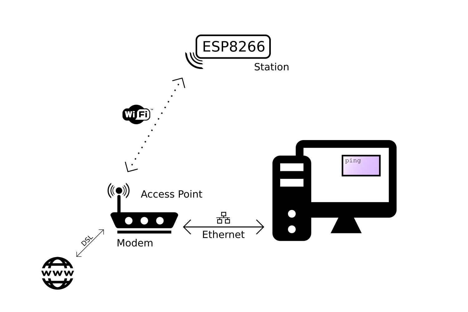
  • Access point: Other Wi-Fi devices can connect to it, to be part of the local network.
  • Router: It routes IP packets to the right sub-nets so that they will arrive at their destination. E.g. if the computer sends a message that is meant for the ESP over the Ethernet sub-net, the router will send the packet to the Wi-Fi sub-net, because it knows that's where the ESP is.
  • Modem: if the router can't find the addressee on the local network, the packet will be passed on to the integrated modem, and it will be sent to the Internet Service Provider over a DSL line, heading for the Internet, where lots of other routers will try to get the packet to the right destination.
But in reality, you don't have to worry too much about it, because it's all done for you, in a fraction of a second without you even noticing it!
 

Automatically connect to the strongest network

The sketch above might be enough for your specific application, but if you need to be able to connect to multiple Wi-Fi networks, for example the Wi-Fi at home and the Wi-Fi at the office, it won't work. 
To solve this problem, we'll use the Wi-Fi-Multi library: You can add as many networks as you like, and it automatically connects to the one with the strongest signal.
 
#include <ESP8266WiFi.h>        // Include the Wi-Fi library
#include <ESP8266WiFiMulti.h>   // Include the Wi-Fi-Multi library

ESP8266WiFiMulti wifiMulti;     // Create an instance of the ESP8266WiFiMulti class, called 'wifiMulti'

void setup() {
  Serial.begin(115200);         // Start the Serial communication to send messages to the computer
  delay(10);
  Serial.println('\n');

  wifiMulti.addAP("ssid_from_AP_1", "your_password_for_AP_1");   // add Wi-Fi networks you want to connect to
  wifiMulti.addAP("ssid_from_AP_2", "your_password_for_AP_2");
  wifiMulti.addAP("ssid_from_AP_3", "your_password_for_AP_3");

  Serial.println("Connecting ...");
  int i = 0;
  while (wifiMulti.run() != WL_CONNECTED) { // Wait for the Wi-Fi to connect: scan for Wi-Fi networks, and connect to the strongest of the networks above
    delay(1000);
    Serial.print('.');
  }
  Serial.println('\n');
  Serial.print("Connected to ");
  Serial.println(WiFi.SSID());              // Tell us what network we're connected to
  Serial.print("IP address:\t");
  Serial.println(WiFi.localIP());           // Send the IP address of the ESP8266 to the computer
}

void loop() { }
 

Access Point mode

To configure the ESP8266 as an access point, to allow other devices like smartphones or laptops to connect to it, you can use the softAP function:
#include <ESP8266WiFi.h>        // Include the Wi-Fi library

const char *ssid = "ESP8266 Access Point"; // The name of the Wi-Fi network that will be created
const char *password = "thereisnospoon";   // The password required to connect to it, leave blank for an open network

void setup() {
  Serial.begin(115200);
  delay(10);
  Serial.println('\n');

  WiFi.softAP(ssid, password);             // Start the access point
  Serial.print("Access Point \"");
  Serial.print(ssid);
  Serial.println("\" started");

  Serial.print("IP address:\t");
  Serial.println(WiFi.softAPIP());         // Send the IP address of the ESP8266 to the computer
}

void loop() { }
 
To see if it works, open the Wi-Fi settings on your computer, look for a network called "ESP8266 Access Point", enter the password "thereisnospoon", and connect to it. Then open a terminal, and ping to 192.168.4.1 (this is the default IP address of our ESP AP). You'll see that the ESP responds to your pings. 
 
However, if you try to go to an online website, you'll get a timeout or a DNS error. This is because the ESP itself is not connected to the internet. The sub-net that consists of the ESP and the computer is not connected to any other networks, so there's no way for a packet on this network to make it to the Internet.
 
If you connected a second station to the ESP access point on the other hand, you would be able to ping from one station to the other without problems, because they're on the same network.

Uploading sketches to the ESP8266
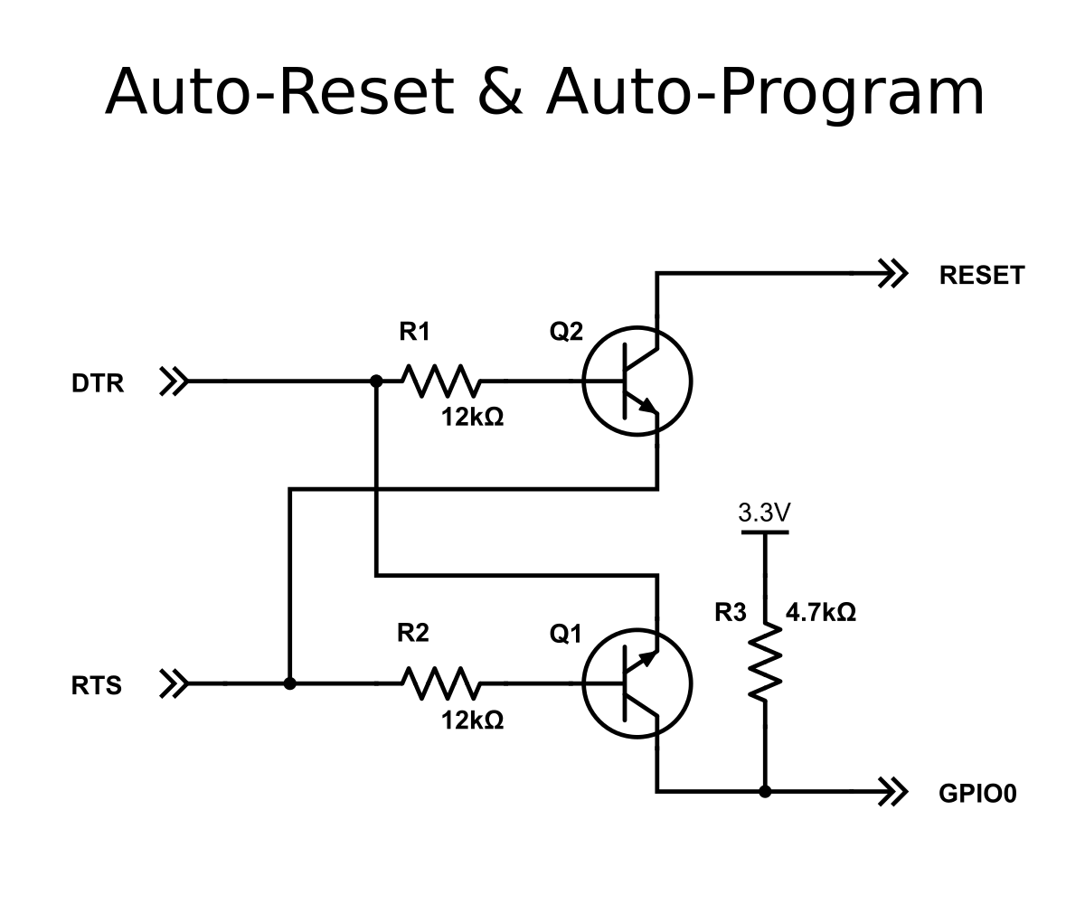
The upload procedure for ESP8266 boards is a little different from the normal Arduino procedure. Most Arduinos will automatically reset when a new program is being uploaded, and will automatically enter programming mode.
On some ESP boards you have to manually enter programming mode, and on the bare-bones modules, you even have to reset them manually.
However, there are some simple circuits you can use to get automatic uploads.

Auto-reset

This only applies to boards without an on-board USB-to-Serial converter.
 
If the USB-to-Serial converter you're using has a DTR flow control line, you can automate the reset signal. When sending data to the ESP, the DTR line goes low, and stays low for some time. To reset the ESP, we need a low pulse on the RST pin. The problem is that the DTR pin stays low. To solve this, we're going to build a crude edge detector circuit, using a capacitor. Take a look at the following schematic:
 
reset_without_diode.png
You might recognize that this is basically a low-cut filter. In normal conditions, DTR is high (3.3V), and the reset line is also high, because of the pull-up resistor R2. This means that the voltage across the capacitor is 0V. When DTR suddenly drops (to 0V), the voltage across the capacitor is still 0V, meaning that the reset line will be at 0V + 0V = 0V, and a reset is triggered.
 
However, C1 immediately starts charging through R2, and reaches 3.3V. At this point, DTR is still at 0V, meaning that there's now 3.3V across the capacitor. When DTR rises again, the reset line will be at 3.3V + 3.3V = 6.6V, and then immediately starts to discharge through R2, finally reaching 3.3V again, with 0V across C1.
This is a problem: 6.6V can damage the ESP, so we have to find a way to get rid of the positive peak.
 
One glance at this MATLAB simulation shows us the problem even better:
 

without_diode.png

The blue signal is the voltage on the DTR pin, and the yellow signal is the voltage on the reset pin.
 
The solution is to add a diode: while charging the capacitor, it shouldn't change anything, so it should be reverse biased (just a fancy way of saying that it's not conducting any current because the polarity is the other way around), and while the capacitor is discharging, it should discharge the capacitor "immediately".
Here's what that looks like:
 
reset_with_diode.png
Let's run the simulation again to check if our problem is solved:
 
with_diode.png
 
As you can see, the 6.6V peak is now very narrow, just like we wanted. It's impossible to discharge the capacitor instantly, that would require a capacitor and a diode with 0Ω of series resistance, and an infinite current, which is impossible, obviously. There's also a smaller but relatively wide peak of approximately 3.9V. This is because a diode only conducts when the voltage across it is higher than ~600mV. This means that the last 0.6V that's left in the capacitor (from 3.9 to 3.3V) will still be discharged through R2 only. 
Nevertheless, the voltage peak is much lower and narrower than without the diode, and it's safe to connect to the ESP8266.
 
This exact circuit is also used in the Arduino Uno, for example.
 
Note: if you followed the instructions in the hardware step correctly, you should already have added R2 to your ESP.

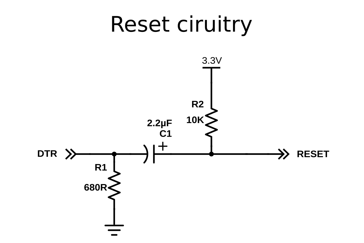
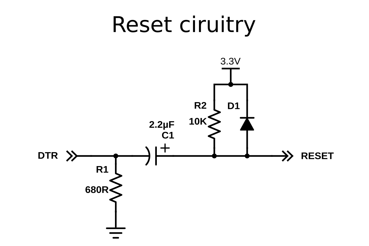
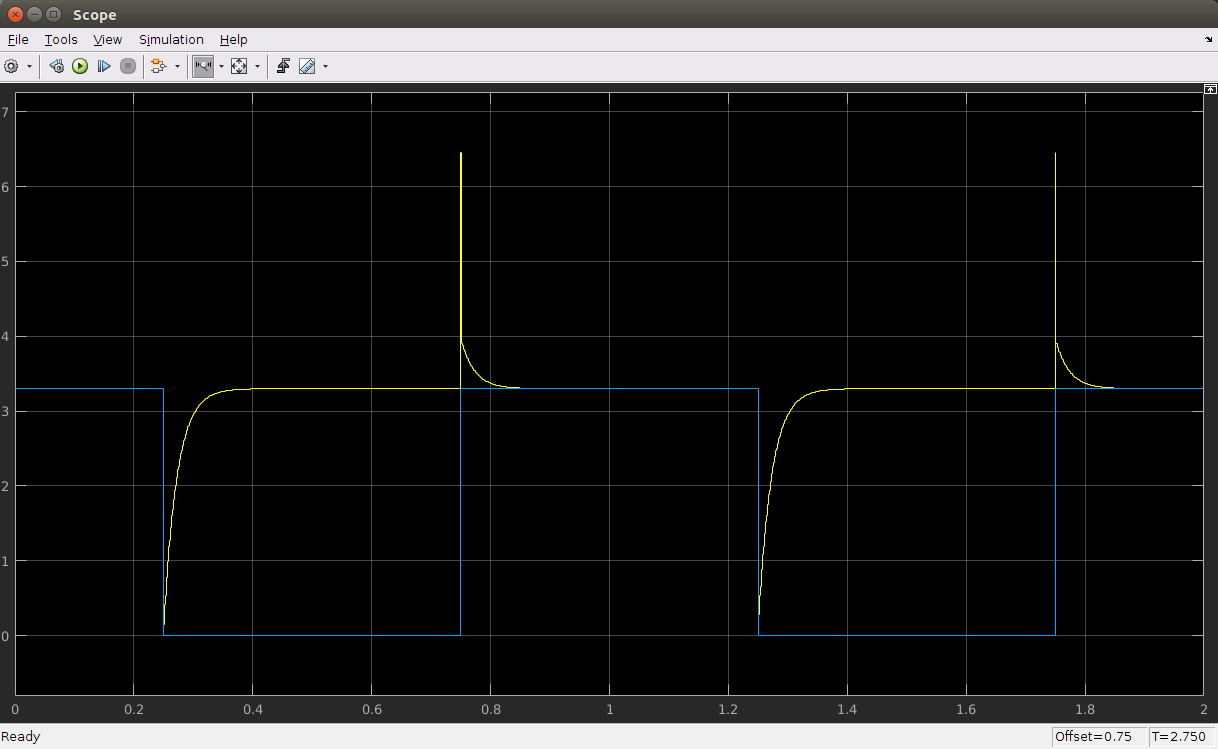
How to use Auto-reset

To use this auto-reset circuit, connect it to the DTR line of your USB-to-Serial converter, and to the reset line of the ESP, as shown in the diagram. Then click compile (just because the first compilation can take quite some time). Go to Tools > Reset and select 'ck'. When it's done compiling, hold down the program button we added in the hardware step, and click upload. Wait for it to say "Uploading..." and then release the program button.

Auto-reset and Auto-program

This only applies to boards without an on-board USB-to-Serial converter.
 
The method above still requires you to press a button to upload a new sketch. If your USB-to-Serial converter has a RTS line as well as a DTR line, you can automate the entire process.
auto-reset_auto-program.png
You may find out that the 4.7kΩ resistor doesn't work for you. In that case, try some other value, like 10kΩ, for example.
 
This method was first used in the NodeMCU, so go to Tools > Reset Method, and select "nodemcu". This will drive the DTR&RTS pins high and low in the right sequence to get it in programming mode before uploading.
 
This is by far the best method, but the problem is that you need access to both the RTS and DTR pins, while most USB-to-Serial adapters break out only one of the two.
 

Manual reset and manual program

This only applies to boards without an on-board USB-to-Serial converter.
 
If you don't have a USB-to-Serial converter with DTR and RTS lines, you could also just use the reset and program buttons we added in the hardware chapter. To get the ESP in program mode, GPIO0 must be low while booting: 
  1. press and hold the reset button
  2. press and hold the program button
  3. release the reset button, the ESP will boot in program mode
  4. release the program button
  5. upload the sketch
If you want to get out of program mode without uploading, just press reset (without pressing the program button).

Board options

If your specific board is in the Tools > Board list (e.g. NodeMCU, SparkFun and Adafruit boards), you can just select it, and you will get the right settings. When your board isn't in the list, you'll have to select a Generic ESP8266. In that case there's lots of new options in the Tools menu of the Arduino IDE, so let's go over them and pick the right settings.
 

Flash Mode

Like I said before, the ESP8266 uses an external flash chip for storage. You can communicate with this chip over 2 datalines (DIO), or over all 4 datalines (QIO). Using 4 lines is two times faster than 2 lines, so in most cases, you should choose QIO. (If you're doing some advanced stuff and you need 2 more GPIO pins, you could use 2 lines instead of 4, and use the 2 lines as I/O. Most modules don't give you access to these pins, though. )

Flash Size

Different boards/modules have different sizes of flash chips on board. There are boards with 512kB, 1MB, 2MB and 4MB of flash. To know how much flash your board has, you can try the Examples > ESP8266 > CheckFlashConfig to see if your flash setting is correct, or you can check the specifications of your specific board online.
You can also select the SPIFFS (SPI Flash File System) size. The SPIFFS partition is a small file system to store files. If you're not using it, you can select the minimum. Later on in the article, we'll use SPIFFS, and I'll remind you to select a larger SPIFFS size, but for now, it doesn't really matter.

Debug port

There's a load of things going on when the ESP is running: Things like Wi-Fi connections, TCP connections, DNS lookups ... you name it. All these small tasks produce a whole lot of debug output to help you troubleshoot. However, in a normal situation, where your program is behaving as expected, you don't need all those debug messages to flood the Serial Monitor, so you can just turn them off by selecting 'Disabled'. 
If you do wish to receive debug messages, you can select the port to send them to. (Serial on pins 1 and 3, or Serial1 on pin 2)

Debug level

This allows you to choose what kind of debug messages you want to show.

Reset Method

As mentioned in the paragraphs above, there are different methods for auto-reset and auto-program. If you're using the first method (using the edge detector), you should use 'ck', if you use the two-transistor circuit, select 'nodemcu'.

Flash Frequency

If you need some extra memory speed, you could change the flash frequency from 40MHz to 80MHz. This is the clock frequency of the SPI/SDIO link.

CPU Frequency

If you need some extra CPU performance, you can double the clock speed from 80MHz to 160MHz. It's actually an overclock, but I've never had any issues or instability. 

Upload Speed

The baud rate for uploading to the ESP. The default is 115200 baud, but you can go higher (if you're changing your sketch a lot, it might be too slow). 921600 baud works most of the time, but you may get an error sometimes, if that's the case, switching back to 115200 will probably solve all problems.

ESP8266 Wi-Fi

Using the ESP8266 as a simple microcontroller is great, but the reason why most people use it, is its Wi-Fi capabilities. In this chapter, we'll dive into the wonderful world of network protocols, like Wi-Fi, TCP, UDP, HTTP, DNS ... All these acronyms might intimidate you, but I'll try my best to explain them step-by-step and in an easy way.
 
Some paragraphs are in italic. These provide some extra information, but are not critical to understanding the ESP's Wi-Fi functions, so don't get frustrated if there are things you don't understand.
 
It's really hard to give a clear explanation, without over-complicating things and while keeping it short enough as well. If you've got any feedback or remarks, be sure to leave a comment to help improve this article. Thanks!

The TCP/IP stack

The system most people refer to as 'The Internet' isn't just one protocol: it's an entire stack of layers of protocols, often referred to as the TCP/IP stack. We'll go over these different layers, because we need to understand how our ESP8266 communicates with other devices on the network.
 
LayerProtocols
Application HTTP, FTP, mDNS, WebSocket, OSC ...
Transport TCP, UDP
Internet IP
Link Ethernet, Wi-Fi ...

The Link layer

The link layer contains the physical link between two devices, an Ethernet cable, for example, or a Wi-Fi connection. This is the layer that is closest to the hardware.
To connect an ESP8266 to the network, you have to create a Wi-Fi link. This can happen in two different ways:
  1. The ESP8266 connects to a wireless access point (WAP or simply AP). The AP can be built-in to your modem or router, for example. 
    In this configuration, the ESP acts like a wireless station. 
  2. The ESP8266 acts as an access point and wireless stations can connect to it. These stations could be your laptop, a smartphone, or even another ESP in station mode.
Once the Wi-Fi link is established, the ESP8266 is part of a local area network (LAN). All devices on a LAN can communicate with each other.
Most of the time, the AP is connected to a physical Ethernet network as well, this means that the ESP8266 can also communicate with devices that are connected to the AP (modem/router) via a wired Ethernet connection (desktop computers, gaming consoles and set-top boxes, for instance).
If the ESP8266 is in station mode, it can communicate with any station that is connected to it, and two stations (e.g. a laptop and a smartphone) can also communicate with each other.
 
The ESP can be used in AP-only, station-only, or AP+station mode.
 

TL;DR

The link layer is the physical link between devices: in the case of the ESP8266, this is a WiFi connection. The ESP can act as a station and connect to an access point, or act as an access point and let other devices connect to it.
 

The Internet or Network layer

Although the devices are now physically connected (either through actual wires (Ethernet) or through radio waves (Wi-Fi)), they can't actually talk to each other yet, because they have no way of knowing where to send the message to. 
That's where the Internet Protocol (IP) comes in. Every device on the network has a personal IP address. The DHCP server (Dynamic Host Configuration Protocol Server) makes sure that these addresses are unique. 
This means that you can now send a message to a specific address.
 
There are two versions of the Internet Protocol: IPv4 and IPv6. IPv6 is an improved version of IPv4 and has much more addresses than IPv4 (because there are much more devices than available IPv4 addresses). In this article, we'll only talk about IPv4 addresses, since most LANs still use them.
 
The IP address consists of 4 numbers, for example 192.168.1.5 is a valid IPv4 address. It actually consists of two parts: the first part is 192.168.1, this is the address of the local network. The last digit, 5 in this case, is specific to the device. 
 
By using IP addresses, we can find the ESP8266 on the network, and send messages to it. The ESP can also find our computer or our phone, if it knows their respective IP addresses.
 

Sub-net mask (optional)

This subdivision of the IP address is determined by the sub-net mask, often written as 255.255.255.0. You can see that it consists of four numbers, just like the IP address. If a part of the sub-net mask is 255, it means that the corresponding part of the IP address is part of the network address, if it's 0, the corresponding IP part is part of the address of the specific address. A different notation to "IP: 192.168.1.5, sub-net mask: 255.255.255.0" would be "192.168.1.5/24", because the binary representation of the sub-net mask is 11111111.11111111.11111111.00000000, and it has 24 ones.
If you want to know more about sub-nets, I'd recommend you to read the Wikipedia article
(A quick tip to help you remember: it's called the sub-net mask, because if you perform a bitwise AND operation on the IP address and the sub-net mask (i.e. use the sub-net mask as a mask for the IP address), you get the address of the sub-net.)
 

MAC addresses and ARP (optional)

It is actually impossible to send packets directly to another machine using only the IP address. To send a packet to a specific device on the LAN (Wi-Fi or Ethernet), you have to know its MAC-address. The MAC address is a unique number that is unique for every network device, and it never changes, it's hardwired in the network chip. This means that every ESP8266, every network card, every smartphone ... ever made, has a different MAC address. 
So before the ESP can send a packet to your smartphone for example, it has to know its MAC address. It doesn't know this yet, the ESP only knows the IP address of the smartphone, say 192.168.1.6. To do this, the ESP sends a broadcast message (i.e. a message addressed to all devices on the LAN) saying "I'm looking for the MAC address of the device with the IP address 192.168.1.6". The ESP also includes its own IP and MAC address with the message. When the smartphone receives this broadcast message, it recognizes its own IP address, and responds to the ESP by sending its own MAC address. Now the ESP and the phone both know each other's IP and MAC addresses, and they can communicate using IP addresses. This method is called the Addres Resolution Protocol, or ARP.
 

What about the Internet?

As you might have noticed, I only talked about the local area network, these are the computers in your own house. So how can the ESP8266 communicate with the Internet, you may ask? Well, there's a lot of network infrastructure involved in 'The Internet', and they all obey the IP rules, to make sure most of your packets arrive at there destination. It's not that simple of course, there's a lot of things going on, like routing and Network Address Translation (NAT), but that falls outside the scope of this article, and it's not really something most people have to worry about.
 

TL;DR

The Internet layer uses IP addresses in order to know where it should send the data. This means that two devices can now send packets of data to each other, even over the Internet.
 

The Transport layer

The different devices in the network do their best to deliver these IP packets to the addressee, however, it's not uncommon for a packet to get lost, so it will never arrive. Or the packet might get corrupted on the way: the data is no longer correct. IP also can't guarantee that the packets arrive in the same order they were sent in.
This means that we can't reliably send messages yet by only using the link and the Internet layer, since we can never know when and whether a packet will arrive, or know for certain that a received packet is correct.
We need a third layer on top of the Internet layer: the Transport layer.
 
There are mainly two protocols that make up this third layer: the Transmission Control Protocol (TCP) and the User Datagram Protocol (UDP).
  • TCP makes sure that all packets are received, that the packets are in order, and that corrupted packets are re-sent. This means that it can be used for communication between multiple applications, without having to worry about data integrity or packet loss. This is why it's used for things like downloading webpages, sending email, uploading files etc.
  • UDP on the other hand, doesn't guarantee that every packet reaches its destination, it does check for errors however, but when it finds one, it just destroys the packet, without re-sending it. This means that it's not as reliable as TCP, but it's faster, and has a much lower latency, because it doesn't require an open connection to send messages, like TCP does. That's why it's used in voice and video chats, and for example in online games.
If you want to know more about the differences between TCP and UDP, check out this video.

TL;DR

The IP protocol is not reliable, and has no error checking. TCP solves this by re-sending lost or corrupt packages, and orders packets that are received in the wrong order. UDP also checks for corrupt packages, but doesn't re-send them, so it has less latency than TCP.
 

The Application layer

We now have reliable communication using TCP, but there's still one problem. Think of it this way: you are sending a letter, and TCP guarantees that it will arrive at its destination, but if the receiver doesn't understand the language it's written in, he won't know what to do with it.
In other words, we need a fourth layer of protocols, for two programs to be able to communicate with each other.
There's lots of different protocols out there, but we'll mostly focus on the protocols for web servers and browsers.

HyperText Transfer Protocol 

The HyperText Transfer Protocol, or HTTP, is the protocol (cfr. language) that is used by both web servers and web clients in order to communicate. It uses text to perform send requests and responses from the client to the server and back again.
For example, when you type http://www.google.com into the address bar of a web browser (client), it will send an HTTP GET request to the Google web server. The server understands this HTTP request, and will send the Google webpage as a response. Or when you upload an image to Instagram, your browser sends an HTTP POST request with your selfie attached to the Instagram server. The server understands the request, saves the image and adds it into the database, sends the URL of the new image back to your browser, and the browser will add the image on the webpage.
As you can see, neither the client nor the server has to worry about the integrity of the messages they send, and they know that the recipient understands their language, and that it will know what to do with a certain HTTP request. 
Most modern sites use a secure version of HTTP, called HTTPS. This secure connection encrypts the data, for security reasons. (You don't want anyone reading the packets from your mail server, or the packets you sent to your bank, for instance.)

WebSocket

HTTP is great for things like downloading webpages, uploading photos etc. but it's quite slow: every time you send an HTTP request, you have to start a new TCP connection to the server, then send your request, wait for the server to respond, and download the response. Wouldn't it be great if we didn't have to open a new connection every time we want to send some data, and if we could send and receive data at the same time at any moment we'd like? That's where WebSocket comes to the rescue: you can keep the TCP connection with the server open at all times, you get perfect TCP reliability, and it's pretty fast.

Open Sound Control

HTTP and WebSocket both use TCP connections. What if I want lower latency? Well, Open Sound Control, or OSC, uses UDP to send small pieces of data, like ints, floats, short text etc ... with very low latency. It was originally designed for controlling low latency audio applications, but it's a very flexible protocol, so it's often used for low-latency tasks other than audio control.

Domain Name System

As mentioned before, you can only send a message to another computer if you know its IP address. But when you browse the Internet, you only know a website's domain name (e.g. www.google.com). Your computer uses the Domain Name System to translate this domain name to the right IP address. More on this later.
 

Sources

The ESP8266 as a microcontroller - Hardware

While the ESP8266 is often used as a ‘dumb’ Serial-to-WiFi bridge, it’s a very powerful microcontroller on its own. In this chapter, we’ll look at the non-Wi-Fi specific functions of the ESP8266.

Digital I/O

Just like a normal Arduino, the ESP8266 has digital input/output pins (I/O or GPIO, General Purpose Input/Output pins). As the name implies, they can be used as digital inputs to read a digital voltage, or as digital outputs to output either 0V (sink current) or 3.3V (source current).

Voltage and current restrictions

The ESP8266 is a 3.3V microcontroller, so its I/O operates at 3.3V as well. The pins are not 5V tolerant, applying more than 3.6V on any pin will kill the chip.

The maximum current that can be drawn from a single GPIO pin is 12mA.

Usable pins

The ESP8266 has 17 GPIO pins (0-16), however, you can only use 11 of them, because 6 pins (GPIO 6 - 11) are used to connect the flash memory chip. This is the small 8-legged chip right next to the ESP8266. If you try to use one of these pins, you might crash your program.

GPIO 1 and 3 are used as TX and RX of the hardware Serial port (UART), so in most cases, you can’t use them as normal I/O while sending/receiving serial data.

Boot modes

As mentioned in the previous chapter, some I/O pins have a special function during boot: They select 1 of 3 boot modes:

GPIO15GPIO0GPIO2Mode
0V 0V 3.3V Uart Bootloader
0V 3.3V 3.3V Boot sketch (SPI flash)
3.3V x x SDIO mode (not used for Arduino)

Note: you don’t have to add an external pull-up resistor to GPIO2, the internal one is enabled at boot.

We made sure that these conditions are met by adding external resistors in the previous chapter, or the board manufacturer of your board added them for you. This has some implications, however:

  • GPIO15 is always pulled low, so you can’t use the internal pull-up resistor. You have to keep this in mind when using GPIO15 as an input to read a switch or connect it to a device with an open-collector (or open-drain) output, like I²C.
  • GPIO0 is pulled high during normal operation, so you can’t use it as a Hi-Z input.
  • GPIO2 can’t be low at boot, so you can’t connect a switch to it.

Internal pull-up/-down resistors

GPIO 0-15 all have a built-in pull-up resistor, just like in an Arduino. GPIO16 has a built-in pull-down resistor.

PWM

Unlike most Atmel chips (Arduino), the ESP8266 doesn’t support hardware PWM, however, software PWM is supported on all digital pins. The default PWM range is 10-bits @ 1kHz, but this can be changed (up to >14-bit@1kHz).

Analog input

The ESP8266 has a single analog input, with an input range of 0 - 1.0V. If you supply 3.3V, for example, you will damage the chip. Some boards like the NodeMCU have an on-board resistive voltage divider, to get an easier 0 - 3.3V range. You could also just use a trimpot as a voltage divider.

The ADC (analog to digital converter) has a resolution of 10 bits.

Communication

Serial

The ESP8266 has two hardware UARTS (Serial ports):
UART0 on pins 1 and 3 (TX0 and RX0 resp.), and UART1 on pins 2 and 8 (TX1 and RX1 resp.), however, GPIO8 is used to connect the flash chip. This means that UART1 can only transmit data.

UART0 also has hardware flow control on pins 15 and 13 (RTS0 and CTS0 resp.). These two pins can also be used as alternative TX0 and RX0 pins.

I²C

The ESP doesn’t have a hardware TWI (Two Wire Interface), but it is implemented in software. This means that you can use pretty much any two digital pins. By default, the I²C library uses pin 4 as SDA and pin 5 as SCL. (The data sheet specifies GPIO2 as SDA and GPIO14 as SCL.) The maximum speed is approximately 450kHz.

SPI

The ESP8266 has one SPI connection available to the user, referred to as HSPI. It uses GPIO14 as CLK, 12 as MISO, 13 as MOSI and 15 as Slave Select (SS). It can be used in both Slave and Master mode (in software).

GPIO overview

GPIOFunctionStateRestrictions
0 Boot mode select 3.3V No Hi-Z
1 TX0 - Not usable during Serial transmission
2 Boot mode select
TX1
3.3V (boot only) Don’t connect to ground at boot time 
Sends debug data at boot time
3 RX0 - Not usable during Serial transmission
4 SDA (I²C) - -
5 SCL (I²C) - -
6 - 11 Flash connection x Not usable, and not broken out
12 MISO (SPI) - -
13 MOSI (SPI) - -
14 SCK (SPI) - -
15 SS (SPI) 0V Pull-up resistor not usable
16 Wake up from sleep - No pull-up resistor, but pull-down instead 
Should be connected to RST to wake up

The ESP8266 as a microcontroller - Software

Most of the microcontroller functionality of the ESP uses exactly the same syntax as a normal Arduino, making it really easy to get started.

Digital I/O

Just like with a regular Arduino, you can set the function of a pin using pinMode(pin, mode); where pin is the GPIO number*, and mode can be either INPUT, which is the default, OUTPUT, or INPUT_PULLUP to enable the built-in pull-up resistors for GPIO 0-15. To enable the pull-down resistor for GPIO16, you have to use INPUT_PULLDOWN_16.

(*) NodeMCU uses a different pin mapping, read more here. To address a NodeMCU pin, e.g. pin 5, use D5: for instance: pinMode(D5, OUTPUT);

To set an output pin high (3.3V) or low (0V), use digitalWrite(pin, value); where pin is the digital pin, and value either 1 or 0 (or HIGH and LOW).

To read an input, use digitalRead(pin);

To enable PWM on a certain pin, use analogWrite(pin, value); where pin is the digital pin, and value a number between 0 and 1023.

You can change the range (bit depth) of the PWM output by using analogWriteRange(new_range);

The frequency can be changed by using analogWriteFreq(new_frequency);new_frequency should be between 100 and 1000Hz.

Analog input

Just like on an Arduino, you can use analogRead(A0) to get the analog voltage on the analog input. (0 = 0V, 1023 = 1.0V).

The ESP can also use the ADC to measure the supply voltage (VCC). To do this, include ADC_MODE(ADC_VCC); at the top of your sketch, and use ESP.getVcc(); to actually get the voltage.
If you use it to read the supply voltage, you can’t connect anything else to the analog pin.

Communication

Serial communication

To use UART0 (TX = GPIO1, RX = GPIO3), you can use the Serial object, just like on an Arduino: Serial.begin(baud).

To use the alternative pins (TX = GPIO15, RX = GPIO13), use Serial.swap() after Serial.begin.

To use UART1 (TX = GPIO2), use the Serial1 object.

All Arduino Stream functions, like read, write, print, println, ... are supported as well.

I²C and SPI

You can just use the default Arduino library syntax, like you normally would.

Sharing CPU time with the RF part

One thing to keep in mind while writing programs for the ESP8266 is that your sketch has to share resources (CPU time and memory) with the Wi-Fi- and TCP-stacks (the software that runs in the background and handles all Wi-Fi and IP connections). 
If your code takes too long to execute, and don’t let the TCP stacks do their thing, it might crash, or you could lose data. It’s best to keep the execution time of you loop under a couple of hundreds of milliseconds.

Every time the main loop is repeated, your sketch yields to the Wi-Fi and TCP to handle all Wi-Fi and TCP requests.

If your loop takes longer than this, you will have to explicitly give CPU time to the Wi-Fi/TCP stacks, by using including delay(0); or yield();. If you don’t, network communication won’t work as expected, and if it’s longer than 3 seconds, the soft WDT (Watch Dog Timer) will reset the ESP. If the soft WDT is disabled, after a little over 8 seconds, the hardware WDT will reset the chip.

From a microcontroller’s perspective however, 3 seconds is a very long time (240 million clockcycles), so unless you do some extremely heavy number crunching, or sending extremely long strings over Serial, you won’t be affected by this. Just keep in mind that you add the yield(); inside your for or while loops that could take longer than, say 100ms.

Sources

This is where I got most of my information to writ this article, there’s some more details on the GitHub pages, if you’re into some more advanced stuff, like EEPROM or deep sleep etc.