AI-Thinker ESP8266 Black Board T5 (ESP-13)
Product descriptionThe Black Board T5 is based on the ESP8266 chipset and carries also:
Full Features:
|
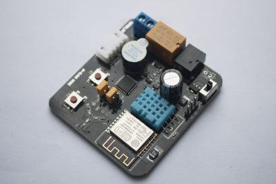 |
ESP8266 T5 ‘Black Board’
AI-Thinker has a dev board which contains a relay, buzzer, a temperature/humidity sensor and a number of different color LEDs, the intention apparently being to provide simple device to start playing with IOT.
However the ‘brains’ of the board is not the ESP-8266 on the board, but is in fact a STC15L2K32S2 microcontroller which unfortunately is what the relay, buzzer, sensor and LEDs are connected to.
However, you can still make use of the ESP-8266 by isolating it from the STC chip.
Accessing the ESP-8266
The ESP-8266 on this board appears to be preprogrammed with the standard ESP-8266 AT command set to interact with the STC chip like a WIFI modem.
Set your serial terminal program to 115200 baud rate and carriage return, line feed both on.
Disconnect the jumpers from WIFI_TX, WIFI_RX.
Connect the serial cable’s Rx lead to the left pin of the pair of pins marked WIFI_RX, the Gnd lead to the WIFI_GND pin and the Tx lead to the left pin of the pair of pins marked WIFI_TX. Enter the following in your serial terminal program to stop the annoying beeping:
Connect the serial cable’s Rx lead to the right pin of the pair of pins marked WIFI_TX, the Gnd lead to the WIFI_GND pin and the Tx lead to the right pin of the pair of pins marked WIFI_RX. Enter AT+GMR in the terminal and the ESP-8266 should respond with something like:
References:
- AI-Thinker forum with some information on the board (in Chinese)
- German forum with some information on removing the STC chip