Barbecue Syllabus
AI-Thinker ESP8266 Black Board T5 (ESP-13)
Product descriptionThe Black Board T5 is based on the ESP8266 chipset and carries also:
Full Features:
|
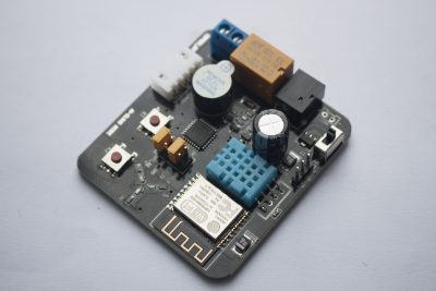 |
ESP8266 T5 ‘Black Board’
AI-Thinker has a dev board which contains a relay, buzzer, a temperature/humidity sensor and a number of different color LEDs, the intention apparently being to provide simple device to start playing with IOT.
However the ‘brains’ of the board is not the ESP-8266 on the board, but is in fact a STC15L2K32S2 microcontroller which unfortunately is what the relay, buzzer, sensor and LEDs are connected to.
However, you can still make use of the ESP-8266 by isolating it from the STC chip.
Accessing the ESP-8266
The ESP-8266 on this board appears to be preprogrammed with the standard ESP-8266 AT command set to interact with the STC chip like a WIFI modem.
Set your serial terminal program to 115200 baud rate and carriage return, line feed both on.
Disconnect the jumpers from WIFI_TX, WIFI_RX.
Connect the serial cable’s Rx lead to the left pin of the pair of pins marked WIFI_RX, the Gnd lead to the WIFI_GND pin and the Tx lead to the left pin of the pair of pins marked WIFI_TX. Enter the following in your serial terminal program to stop the annoying beeping:
Connect the serial cable’s Rx lead to the right pin of the pair of pins marked WIFI_TX, the Gnd lead to the WIFI_GND pin and the Tx lead to the right pin of the pair of pins marked WIFI_RX. Enter AT+GMR in the terminal and the ESP-8266 should respond with something like:
References:
- AI-Thinker forum with some information on the board (in Chinese)
- German forum with some information on removing the STC chip
ARDUINO BASIC PC WITH VGA OUTPUT
Step 1: Build the Arduino Master With TinyBasic and PS2 Keyboard
TinyBasic Plus and the VGAx library work for Arduino IDE 1.6.4.
First download it from the Arduino official web page. If you have a newer versions on your PC, the best is to download it in .zip format and uncompress them on your PC. Click this link to download the Windows version.
You need then the PS2keyboard library. You can find it at the bottom of this page. Just uncompress it and copy the PS2keyboard folder in: arduino-1.6.4\libraries
Finally, in this page, download the file: TinyBasicPlus_PS2_VGAx.ino, uncompress and upload it on your Arduino.
This is a variation of the standard TinyBasic Plus where i have added the PS2 library and modified the code to accept the variables from it.
More details on TiniBasic Plus and tutorials can be found at this link.
If there are no problems, and compatibility issues, Tiny Basic is already running. You can test it trough a serial monitor in your PC. For this purpose I use PuTTY, but many other programs are available.
You have to set the correct COM port (it is the same you find in the Arduino IDE) and baud rate = 4800
Here you can already test some program in Basic just by typing them with your PC keyboard (NB later on I will show how to connect the PS2 keyboard directly to the Arduino).
Try for instance:
10 PRINT "Hello, World!"
20 GOTO 10
RUN
You can then stop the infinite loop just by typing ctrl+c.
Note that this combination will not work for the PS2 keyboard.
In the next step I will show how to connect the PS2 keyboard to Arduino.
Step 2: Connect the PS2 Keyboard to the Master Arduino

I got all the informations and library from this Instructable.
Essentially you need to connect the folowing four pins:
- keyboard Data to Arduino pin 8,
- keyboard IRQ (clock) to Arduino pin 3;
- you need to connenct GND and +5V as well.
I got an old PS2 female connector from a broken PC motherboard. You can simply unsold it with a heat gun.
In the picture shown in this step, you can find the function of the needed pins of the PS2 connector.
Step 3: Upload the VGAx Library and Code on the Second Arduino and Put Everything Together

First download VGAx-PC.ino code at the bottom of this page and copy it on your PC in a directory with the same name.
Download the VGAx library from this link on GitHub. The easiest way is to copy it in the Arduino software subfolder named "libraries", to be immediately recognized.
IMPORTANT: this library works for Arduno IDE 1.6.4 but it is not fully compatible with elder or newer versions.
Upload the VGAx-PC.ino in your second Arduino board (I tested it for the Nano version but the Uno should work as well).
A warning for low available memory is normal. If you do not have other errors everything is ok and you can immediately start to build your own 8-bit PC.
For this you need:
- two Arduino Uno Rev. 3 or two Arduino Nano 3.x (ATmega328)
- a DSUB15 Connector, i.e. a VGA female connector or a VGA cable to be cut.
- resistors: 2 x 68 Ohm and 2 x 470 Ohm
- a PS2 female connector
- wires
- facultative: a breadboard or a strip board
The schematic is reported at the top of this step. An example of a finished “console” is shown in the introductive step.