SP8266 - Easiest way to program so far (Using Arduino IDE)
ESP8266 - Easiest way to program so far (Using Arduino IDE)
Yep, another post on the ESP8266 is here (By the way, Have you heard about our Facebook page already? Like us and get updates! We tend not to spam :P).
It Seems like the ESP8266 community getting larger everyday and great people develop great tools to make the ESP8266 easier to use. (What is the ESP8266? Read some older posts: Flashing, Connecting a relay, Spectrum Analyzer).
The last projects were programmed using the NodeMCU Firmware, which creates a very simple operating system on the ESP8266 and let you write and execute LUA files. It has a lot of advantages which were described in those posts but some disadvantages as well such as memory problems and firmware bugs which the average user cannot resolve.
Recently, some group from the ESP8266 forum published their code on GitHub. The code is an extension to the Arduino IDE which allows to flash programs to the ESP8266, making it kind of arduino compatible - HOORAY!.
As always, in order to try a new method I must decide on a new project which will encourage me to deal the new method with enthusiasm. The project I decided to build was a new code for the Water heater project posted here a while ago. Reviewing the old post, I found its code more or less a "proof-of-concept" code, where the emphasis was on the hardware.
The project description in a few bullets:
- The ESP8266 connects to my router via WiFi and serve as a web-client.
- A website consists of a manageable SQL database with the schedule of the water heater with a main page for the user. The user can add/erase queries from the database.
- Every 5 minutes the ESP8266 sends a GET request to the the website and receive the minutes left to turn ON/OFF the water heater. That way, even if the WiFi fails at some point the ESP8266 will still have the most updated schedule from the website. While sending the GET request, the website saves data of the time of request, the status of the GPIO and the ESP8266 IP address. In the main page the user can see when was the last GET request and identify failures in the ESP8266.
- In case the user can't wait the 5 minutes, the ESP8266 serve as a server as well. From the main page the user can send an "Update" request to the ESP8266 IP address (Which was save before), and the ESP8266 will trigger its update function immediately instead of waiting the 5 minutes.
- In case there's need to change the water heater status, the GPIO which is connected to the relay will change its status (LOW/HIGH).
- All the GET requests are password protected (As secured as my knowledge in the field) to avoid hackers messing around with the database.
Installing and Configuring
To get yourself a working environment go over these steps:
(EDIT 11/2015: I have updated the steps)
- Download the Arduino IDE.
- Go to File --> Preferences and add the link
http://arduino.esp8266.com/stable/package_esp8266com_index.jsonto the Additional Boards Manager URLS.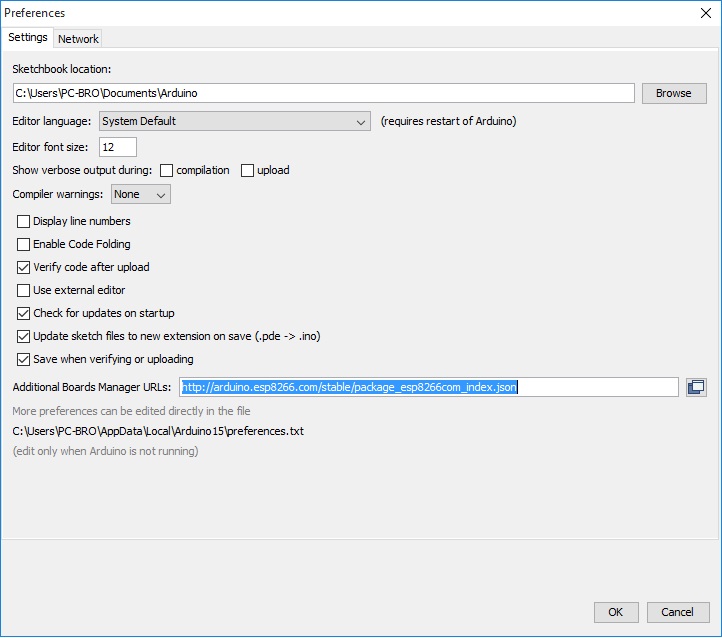
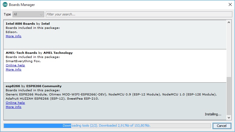
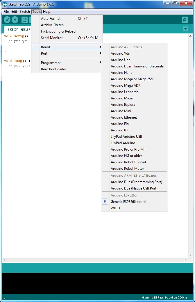
- Go to Tools --> Board --> Boards manager
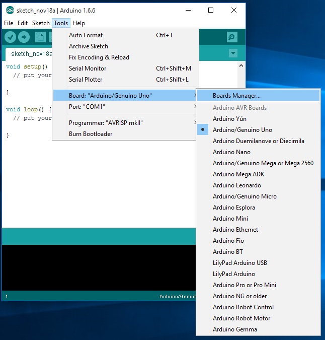
- You should now have the esp8266 as an option there since you've added it to the Additional Boards. Select it and press Install
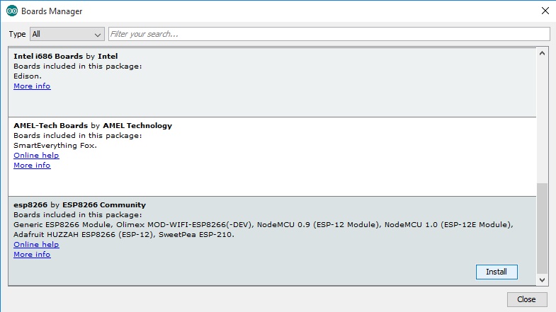
- Wait for it...
- Now, You have the ESP8266 boards configure. Choose the board you have, "Generic ESP8266 Module" if you got the regular module
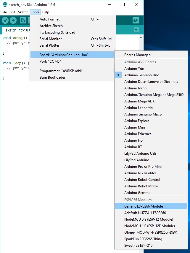
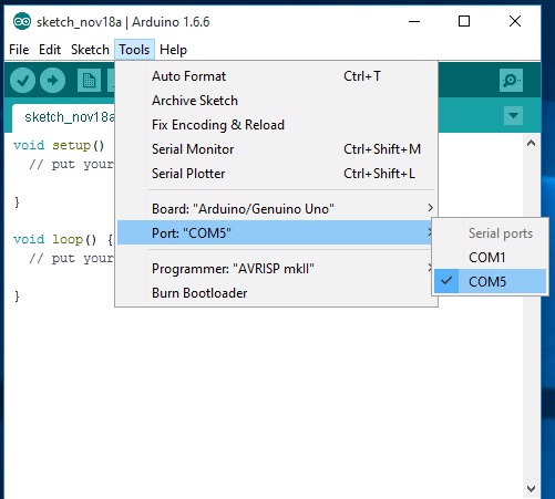
- Choose the ESP8266 port and you're done!
Option 2: Another option, which is less preferable but was the only way available when I first wrote this post is:
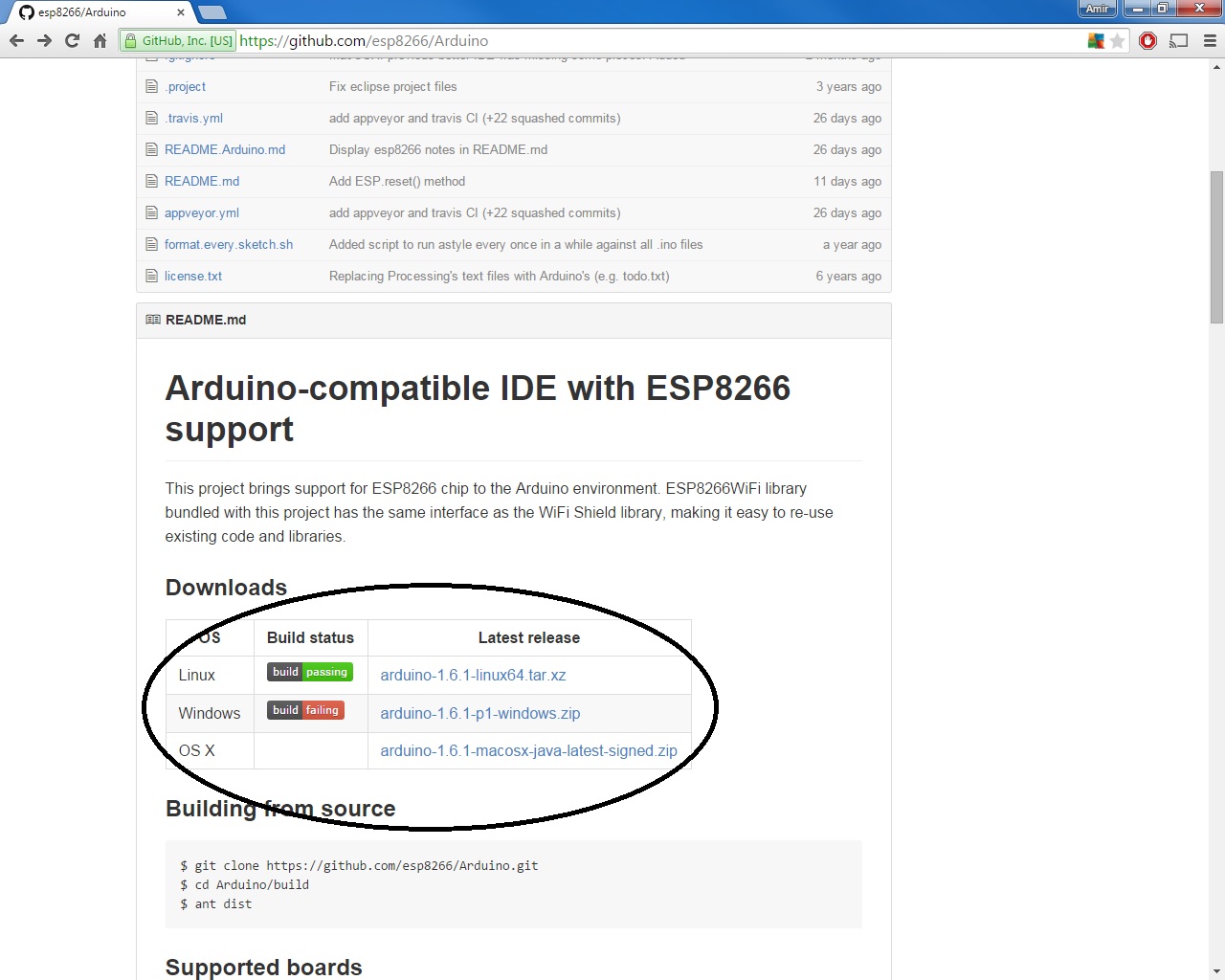
- Download the environment from GitHub (Linux,Window or Mac)
- Install the program. Personally, I use windows so no need for explaination here.
- Choose the port where the ESP8266 is connected.
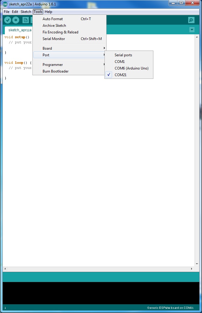
- Choose the ESP8266 from the board lists.
- Choose the esptool as programmer and you're done!.
(EDIT 8/2015: In the current version of this tool the programmer option doesn't exist, and doesn't needed to be configured - Just ignore this step)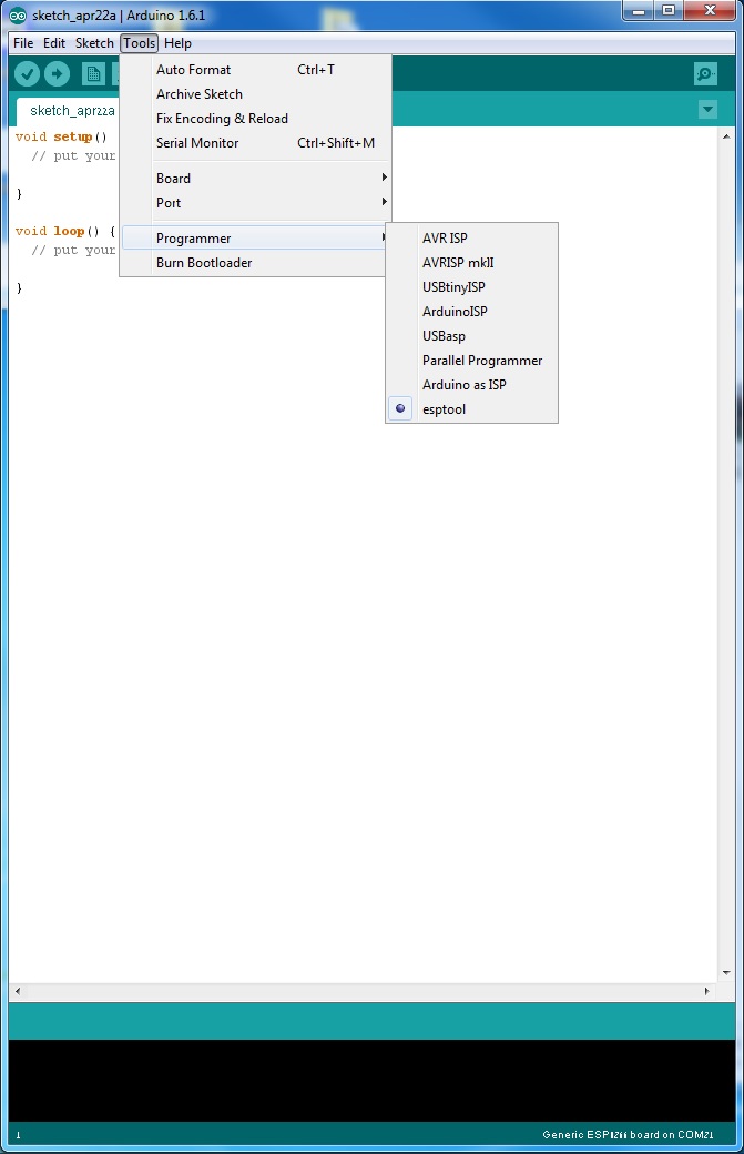
And that's it, you are ready. From what I understood by digging through the files, the new code interpreting the common arduino functions into a clear c++ code, then using the esptool to create a new firmware and flash it on the ESP8266. How come nobody done it earlier ha?
Also, Option 3: Another way to get the enviroment, pointed out to me by the the redditor sej7278, is to download the files from this GitHub repository and put them under your "./Arduino/hardware/" folder. The next time you'll load your arduino IDE you'll have to define the port,board and programmer as explain before and you are ready to go. Some people will find this solution better since they would like to choose with which arduino IDE version they want to integrate with. EDIT 24/6/2016: It seems Option 3 Github link is broken - If you find the link let me know :)
Writing a program to the ESP8266
Flashing a program to the ESP8266 is a bit more annoying than flashing an Arduino. When flashing the arduino, all you have to do is press the reset button and release while you upload a program (or even not doing anything if you have FTDI such as in arduino UNO,MEGA) and the arduino will start uploading. With the ESP8266 you have to reset the micro-controller and start it in flashing mode using the GPIO0-to-Ground already mentioned in some older posts. If you don't have any ESP8266 development board and only the module itself I advice building the next circuit 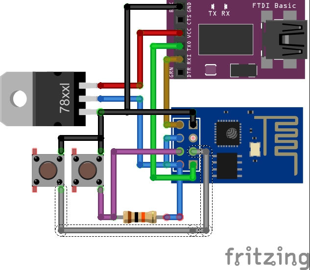 Which will make your life easier. NOTE: The "78xxl" part is actually LM1117 part, did not have it in the Fritzing library.
The sketch shows the formal way to connect ESP8266 to FTDI with a voltage regulator - However, two more buttons have been added. The right button, when pressed, connects the RESET pin to the ground and when it is released, connects the RESET pin to the VCC through a pull-up resistor. The left button, when pressed, connect GPIO0 to the ground. Using this two buttons you can do all the tasks you need with the ESP8266:
- Working on normal mode - Both buttons are released.
- Resetting the ESP8266 - Press the reset button and release.
- Start in flash mode - Press both buttons, release the reset button and then release the GPIO0 button.
My ESP8266 code can be found on GitHub. Check it and you can see it is very similar to an arduino code:
- Starts with a
setup()function. - Followed by a
loop()function. Serialcommands are supported in order to send data to the terminal- Other arduino commands are supported as well.
delay(),millis(),digitalWrite()etc.
In addition, I've included the header file <ESP8266WiFi.h> which completes the other commands needed, among them:
- WiFi library - To connect WiFi simply use the next code:
      WiFi.disconnect();
      WiFi.mode(WIFI_STA);
      WiFi.begin(ssid, password);
-
Client library - With this library you can connect a host (
client.connect()), send a GET request (client.print()), listen and receive data (client.available(),client.readStringUntil('\r')). -
Server library - Allows you to create a server, which upon request (
server.available()) creates a client that will handle the request and send a response.
The rest of the code is just the logic. It starts with all the initial definitions, taken from the TheDudeParams.h file, followed by a definition of the water-heater class which consists of all the useful functions, and then the setup() and loop() functions which handles the connections and the logic. In case of a WiFi problem, the ESP8266 will keep its last records and try to re-connect the WiFi at each time it begins the loop() function.
I'm pretty bad at writing comments in my code so if something is not clear just ask!
Creating the web server
I've used to have some PHP skills which I almost forgot, and no skills at all with SQL so I thought it'll be a good time to learn everything again. I started by getting a domain and hosting-space at GoDaddy, then created there a SQL database. It is very easy to do so using their website but I know some people prefer to ssh-connect the server and do everything by themselves. The main file dude.php is the user page. It produces a web page like that: 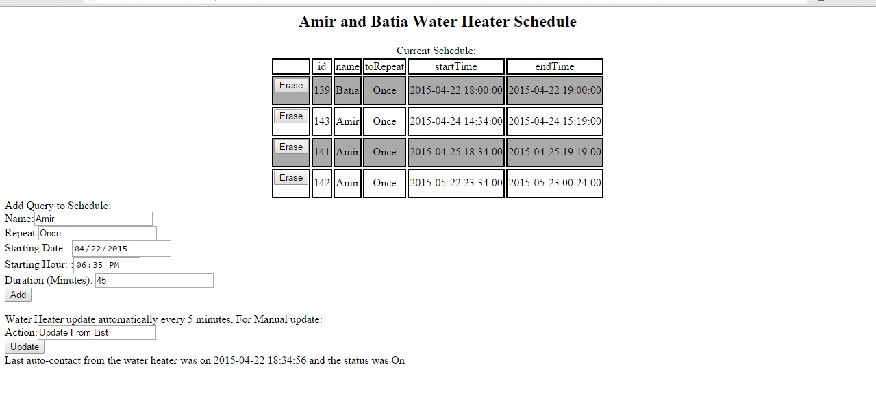 In the page the user can:
- See the entire schedule, ordered by time of activation.
- Erase records.
- Add a new record.
- Send an update request to the ESP8266.
- See when was the last time the ESP8266 synchronized with the server.
After pressing each of the buttons a password must be provided.
Another "behind-the-scenes" file is the getIP.php, which is the file the ESP8266 send requests to. Its main goals:
- Saves a file with the request time, GPIO0 status and the ESP8266 IP address.
- Handle Records:
- Update "Daily" past records to the next day.
- Deletes any non-relevant records (past records).
- Send a push notification if the GPIO0 state has changed (using PushingBox)
- Send response to the ESP8266 with the next ON/OFF schedule.
Both PHP files include the file function.php which consists of some useful SQL handling functions and includes init.php which is the definitions of all the names and passwords.
Final Thoughts
At the moment, the programs are running for a few days now, seems very robust. The idea of sending the ESP8266 only the relevant data was in order to keep its code simple and handle the more complicated code at a higher-level environment. The ESP8266 clock is not a precise clock such as using a RTC chip but if it synchronizes every few minutes with the web it is practical enough.
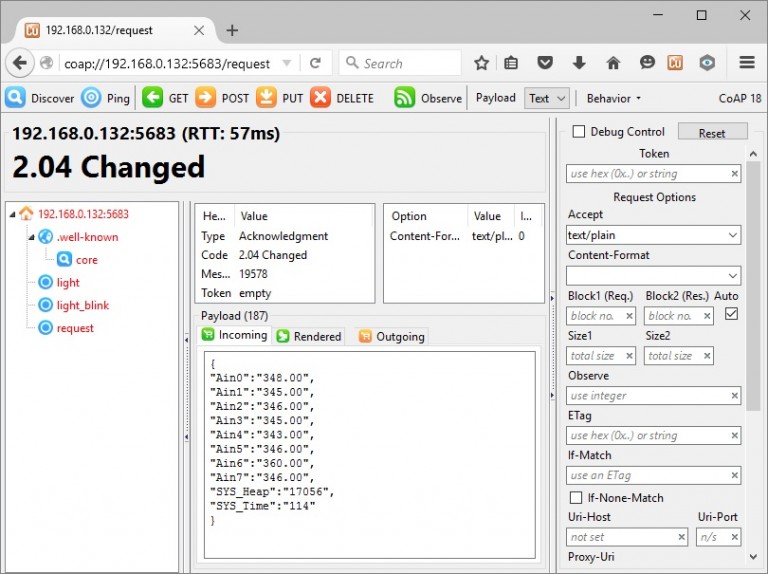
 http://internetofhomethings.com/homethings/wp-content/uploads/2015/12/http-mqtt-coap-300x94.jpg
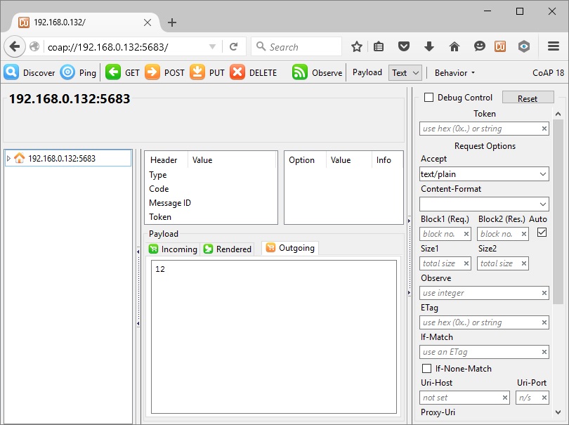 http://internetofhomethings.com/homethings/wp-content/uploads/2015/12/firefox1-300x224.jpg
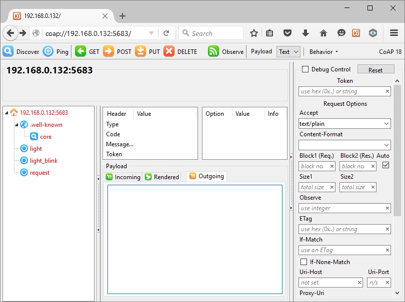 http://internetofhomethings.com/homethings/wp-content/uploads/2015/12/firefox2-300x224.jpg
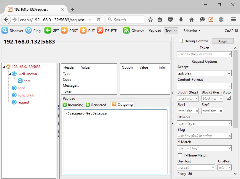 http://internetofhomethings.com/homethings/wp-content/uploads/2015/12/firefox3-300x224.jpg
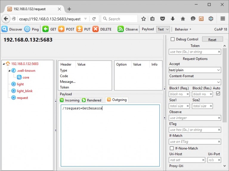
 http://internetofhomethings.com/homethings/wp-content/uploads/2015/12/firefox4-300x224.jpg
4 ways to eliminate ESP8266 resets
If you have worked with the ESP8266 for any length of time, you have undoubtedly experienced the endless resets on power-up. The looping message occurs at about 5 second intervals, which seems to be the default internal watchdog timer time-out period. The message, at 115200 baud, looks something like this:
ets Jan 8 2013,rst cause:4, boot mode:(3,7)
wdt reset
load 0x40100000, len 30000, room 16
tail 0
chksum 0x67
load 0x3ffe8000, len 2556, room 8
tail 4
chksum 0xb7
load 0x3ffe8a00, len 3080, room 4
tail 4
chksum 0x59
csum 0x59
r”
I have yet to come across a definitive explanation for this behavior.
Is this the boot-loader?
The core firmware?
Perhaps a chip defect?
From what I have experienced and read from other users, there are two likely hardware causes that makes logical sense:
- Inadequate power supply interface
- A flash chip failure.
In order to prevent resets, you must include the following three features in the power source to the ESP8266.
- Sufficient current. A regulated 3.3V source of at least 500ma is essential. Aside from the 300ma peak current needs of the ESP8266, it is essential to also consider the current requirements for other components you have – like the sensors and controls in your circuit.
- A large capacitor (suggest using 470 uF) across the Vcc to Gnd rails on your breadboard or PCB is a vital ingredient that will minimize reset inducing voltage fluctuations.
- A 0.1 uF decoupling capacitor across the ESP8266 Vcc to Gnd inputs very close to the pins (within 1/2 inch). DO NOT SKIP THIS COMPONENT! This cheap yet often overlooked component, when missing, is the root cause of ESP8266 resets.
Even with these power supply precautions, we know the flash chip (25Q40) used with many of these ESP8266 module is of low quality and fails after only a few flash cycles. Perhaps sending the code somewhere that it never returns from. Triggering the watchdog timer to reset the unit.
I currently have some replacement flash chips on order and shall see if replacing that chip does indeed remedy the unwanted power-up resets. Unfortunately, my ESP8266-12 (-7 also) has a metal shield over the active components, including the flash chip. This will have to be removed in order to gain access to the memory chip. Removing the shield will require a heat gun—and may very well damage the ESP8266 component. That will be done as last resort, when the reset loops appear to be a permanent condition, rendering the module a “brick”.
But for me, I have not had either of my 2 prototyping ESP8266 assemblies fall into a non-repairable reset loop state yet. If the power supply measures noted above are in place, but you are still experiencing resets, here are a few steps I have been taking with some success to bring back to life an ESP8266 stuck in a ‘Groundhog Day’ reset loop:
Note: Since the entire ESP8266 module is so cheap, if you do not wish to invest your precious time in reviving your module, simply chuck it and start again with another unit. Otherwise, read on, here are 4 methods to correct an ESP8266 stuck repeating reset loops endlessly…
1. Check your connections
This seems obvious. But I have not seen this to be a problem with other MPUs, like an Arduino, Spark Core and even PIC processors.
But my first two ESP8266 set-ups use a standard solder-less breadboard. I have heard that the ESP8266 is very sensitive to intermittent connections, and the solder-less breadboard is not recommended. And sure enough, it has been a problem in my setup. While I have since switched to use soldered contacts on a prototyping vector-board, I am still using the two original breadboards for initial testing. Using these units to limit the flash cycles on the more permanent soldered set-ups.
I have already flashed these 2 initial units a couple hundred times, and counting…
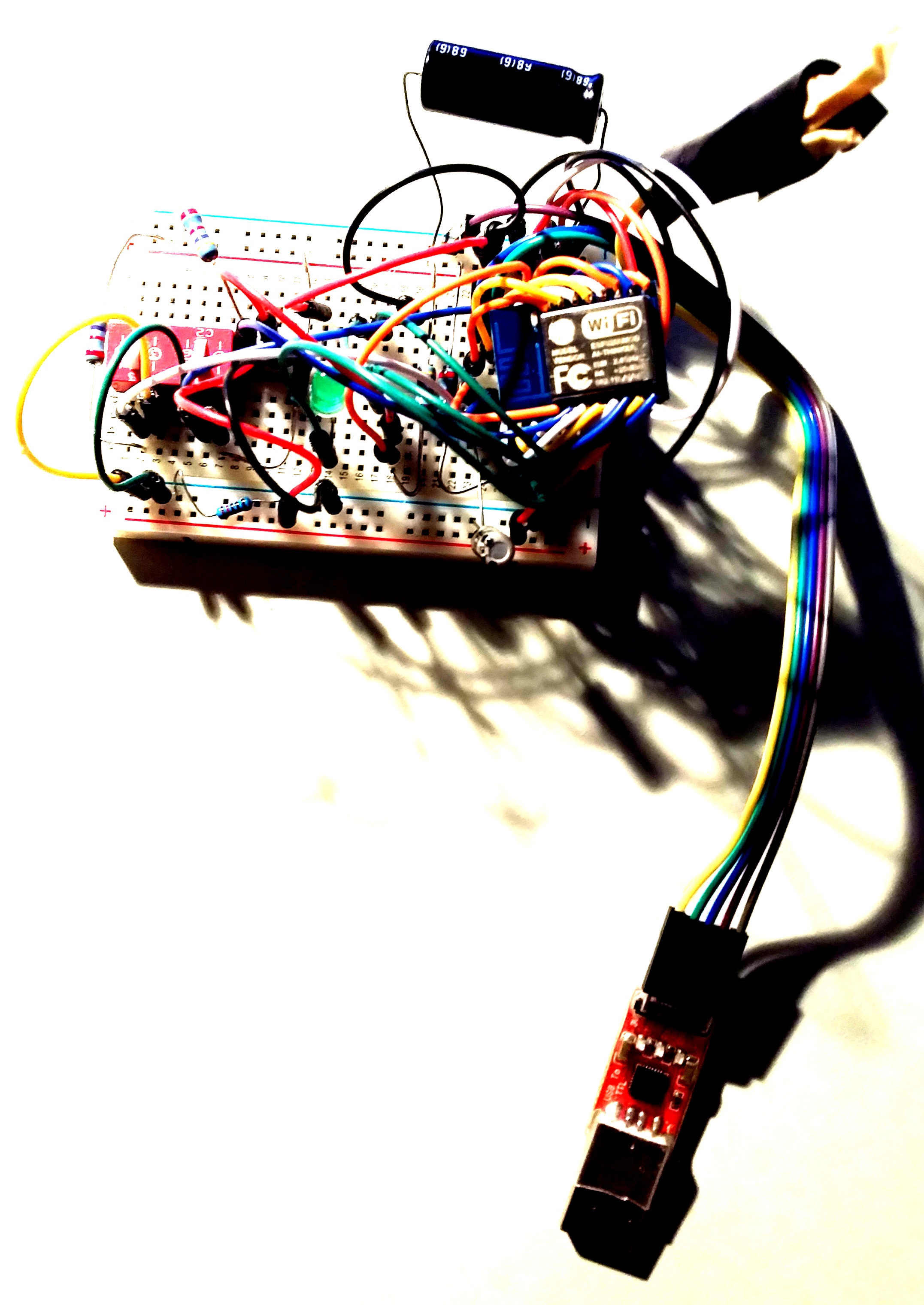 http://internetofhomethings.com/homethings/wp-content/uploads/2015/04/breadboard-725x1024.jpg 725w" sizes="(max-width: 212px) 100vw, 212px" style="box-sizing: border-box; border-width: initial; border-style: none; vertical-align: middle; max-width: 100%; height: auto; display: block; clear: both; margin-left: auto; margin-right: auto; margin-bottom: 10px;">
Solder-less breadboard set-up
After many frustrating and unsuccessful attempts to revive my original setup out of reset purgatory, I made a final inspection of the jumpers and found a few of them only partially engaged.
After securing all the connections again…
The phoenix rose from the ashes. Yes, I had just about given up on this unit And now, the next flash successfully restored the set-up out it’s reset loops. The module was spared the life threatening heat gun!
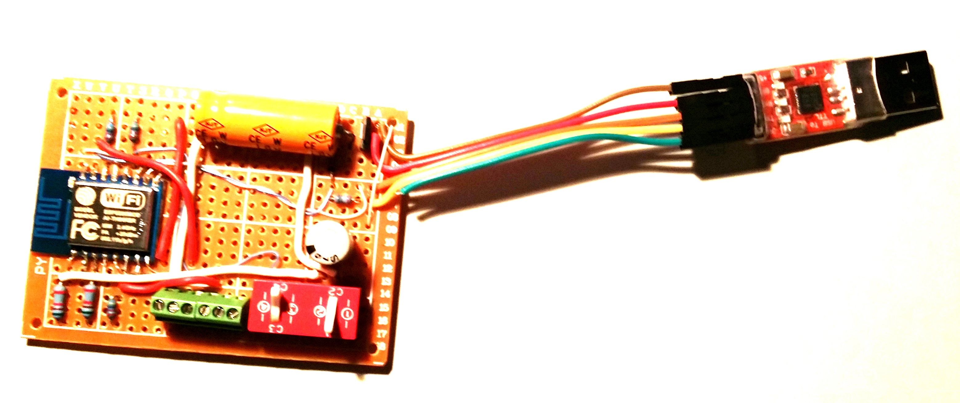 http://internetofhomethings.com/homethings/wp-content/uploads/2015/04/circuitpicture22-1024x430.jpg 1024w" sizes="(max-width: 300px) 100vw, 300px" style="box-sizing: border-box; border-width: initial; border-style: none; vertical-align: middle; max-width: 100%; height: auto; display: block; clear: both; margin-left: auto; margin-right: auto; margin-bottom: 10px;">
Soldered Printed Circuit Board set-up
2. Clear the memory
Along with securing connections, flashing some of the original binaries back into the module has always worked for me to clear the reset problem, so far. As I have already mentioned, it appears that the code gets stuck somewhere that it never returns from, resulting in a wdt reset. This would seem to be as result of corrupted memory. So clearing the flash memory, if possible, should correct the endless reset condition.
Here is what I have found to work:
2.1 Flash AT command set
Flash the ESP8266 with original AT command binary. In case you do not have the flasher, one place to get it:https://drive.google.com/file/d/0B3dUKfqzZnlwVGc1YnFyUjgxelE/view
Restarting the module in normal mode (GPIO2 HI) should result in a 115200 baud start-up message ending with “ready”. And it should respond to the “AT” command with “OK”.
If so, sweet! –-you are good to go.
But it is not always resolved that easily. Sometimes you got to dig deeper. If, your start-up message ends with “jump to user1” and then stops, additional steps will be needed to restore the module.
2.2 Flash blank.bin
Flashing the blank.bin file, which comes with the nodemcu flasher program, is another method to clear the memory. Using the nodemcu flasher, flash the 4K blank.bin to the following 5 starting addresses:
0x00000, 0x01000, 0x40000, 0x7c000, 0x7e000
Then repeat “2.1 Flash AT command set” above.
2.3 Flash blank to the entire 512 kbytes
I have also created a 512 kbyte version of the blank.bin file to clear the entire flash chip. After flashing this file to 0x00000, the entire flash memory address space is cleared.
After clearing the entire flash chip, I have found it necessary to flash the 4 files in the following zip.
https://developer.mbed.org/media/uploads/sschocke/esp_flasher.zip
Once this is complete, again, repeat “2.1 Flash AT command set” above.
3. Replace the flash memory chip
When all else fails, replace the flash memory chip. This involves soldering to remove the faulty 8-pin device and replacing it with a new one. While I do not have a known source to recommend, there are many to choose from on Aliexpress.com. Like the ESP8266, the flash chips are inexpensive, but there is no way to know for sure about the quality. At a minimum, read the reviews from other buyers before placing your order.
4. Software design considerations
There have been problems experienced that could not be overcome using the nodeMCU/lua and SDK development environments. I will write a blog post soon to document those issues. So the following considerations use the Arduino IDE, which is the only development IDE that has been both effective and reliable in implementing my program requirements at this time…
I have yet to find any information that provides the developer much control over the watchdog timer (wdt). The API simply allows you to enable/disable the timer and to “feed” it. I assume “feed” resets the timer although I have not found any documentation to support that assumption. I have found the following steps necessary to eliminate my IoT software application induced resets:
-
The wdt is enabled by default. It should be enabled during normal application operation. If it is disabled in software, instead of resetting, the ESP8266 will halt when a wdt timeout occurs.
-
It is important to return control to the processors periodically. This is done using the yield() or delay() statements. For example, sensor readings requiring more that 0.5 seconds to complete should be followed by a yield() or delay().
-
In addition to yielding control, I have found it necessary to “feed” the wdt periodically to prevent time-consuming tasks from tripping a wdt reset.
Hopefully this helps someone who has struggled with unwanted module resets.
Reworking the AI Thinker T5 – Part VI – Blinkenlights!
Reworking the AI Thinker T5 – Part VI – Blinkenlights!
Okay, now we get to the bit that everyone’s been waiting for; we’re going to connect up the LEDs. Yay!
If you remember back to the original description of the board, I mentioned that there were three LEDs (next to the ESP8266 module) which, with their current-limiting resistors, were arranged in a vaguely spoked shape (and as there are only three spokes, it’s more like an old-fashioned water valve than a bicycle wheel). Unfortunately, the folks who designed the board put the LEDs on the inside of the spokes (with the resistors on the outside), which kinda’ spoils the effect …and also makes them a little more difficult to wire up, as the cathodes are all so close together. In an earlier instalment, I added a short jumper wire between GPIO5 of the ESP8266 and the cathode of the blue LED (which is the one closest to the ESP8266), simply so that I could have some indication that the module was powered on and operational. As with most quick-and-dirty hacks, it has become permanent and, despite the fact that it’s butt-ugly, I’m not planning to change it. That leaves the two others.
 GPIO0 and GPIO2 connections
Going back to the photo of the wiring to switch K1, you can see the short jumper to the blue LED quite clearly. The spoke pointing directly at switch K2 is a green LED and the one pointing directly at the edge of the board is a red LED. It’s also clear from the photo that soldering wires to the cathodes of the two other LEDs would be quite challenging. Luckily, the drive for all three LEDs came from the QFP 8051 chip, so the cathodes of all three are wired to the pads where that unluckydevice used to sit. Equally luckily (for my shaky-handed soldering), the pad for the blue LED is between the other two and, as the blue is already connected, it gives us a little bit of extra clearance to play with when soldering wires onto the green and red pads. The original schematic didn’t identify which LED was which, but our updated (ie:- scribbled on) version has them labelled. As you can see, the drive for the red LED is wired to pad 26 and the green to pad 28, so all we need to do is run wires from spare GPIOs on the ESP to those pads and update our test progam to use them. We’re going to use the adjacent GPIO14 and GPIO12 as our drive pins (GPIO4, on the other side of the module, is also still free, but we’re going to use that later for the connection to switch K2). For GPIO14 and GPIO12, we’ll run the wires around the rather bulky (and, for us, badly placed) smoothing cap sited between the ESP module and the edge of the board, under the DHT11 sensor and directly to the QFP pads (which are on the DHT11 side of the footprint). Again, use super-glue or tiny bits of hot-glue stick, melted with the soldering iron, to hold these (quite long) wires down to the PCB.
After completion, here’s what my board looked like.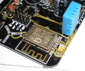 It’s starting to get a little bit crowded around that SMD capacitor, but there’s only one spare GPIO left on that side of the board anyway, so we’re not going to be adding too many more wires.
Updated code is available from the GitHub repository. The new file is named DHT11_Test_Blinken.ino and, in normal Arduino style, must be moved into a directory named DHT11_Test_Blinken to enable compilation. Note that the user_config.h file needs to be available in the same directory and that configuration changes specific to your network must be made in that file prior to compilation (ie:- your access-point SSID and password, your MQTTserver hostname and port-number, etc).
Note that if you’ve already completed the previous rework to connect switch K1 to GPIO0, you can now initiate programming mode on your T5 by turning off the power, holding down K1 and the switching the power back on again. You should be able to release K1 as soon as the board has powered up.
After programming with the “Blinken” code, the coloured LEDs will display a very brief “spinning wheel” at power-on and at all subsequent deep-sleep wake-ups.
The next instalment will cover adding K2 as a “mode control” switch, to change the function of the board at power-up time.
Mobile Sensor #1
IoT, Measuring temperature and light with ESP8266 ESP-12, DS18B20 and LDR.
 |
 |