ESP8266 Advanced
DNS Captive Portal
Wi-Fi configuration
I²S
Other examples
YouTube
ESP8266 Email notifier
Another great use for IoT devices is displaying things like traffic information, weather forecast, social media updates ... This requires us to send an HTTP GET request to the server of the service we'd like to access. Most popular services have API (Application Programming Interface) documents that explain that explain how you can retrieve certain information, and what format that information is in. In the following example, we'll look at Gmail specifically, but the code should be similar for other services.
Showing the number of unread emails
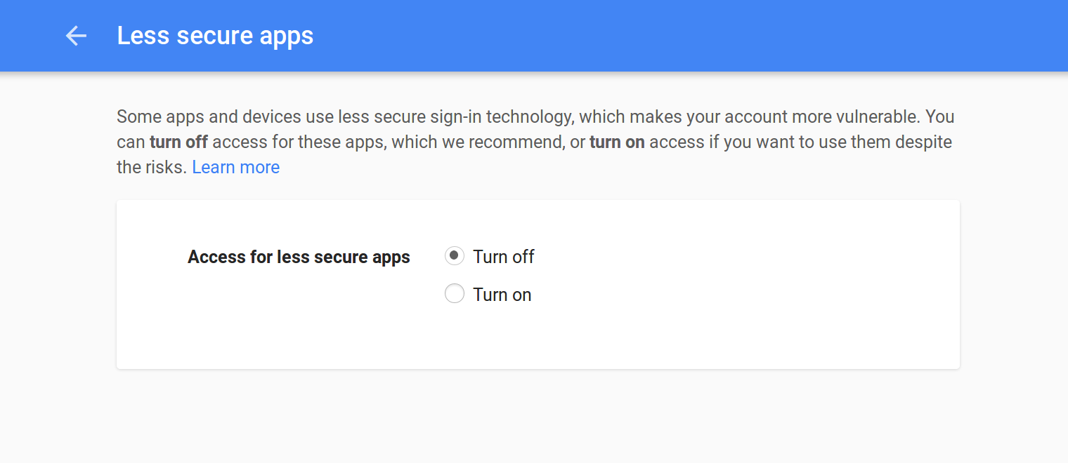
Allowing access to the email feed

Hardware
The Code
#include <WiFiClientSecure.h>   // Include the HTTPS library
#include <ESP8266WiFi.h>        // Include the Wi-Fi library
#include <ESP8266WiFiMulti.h>   // Include the Wi-Fi-Multi library

ESP8266WiFiMulti wifiMulti;     // Create an instance of the ESP8266WiFiMulti class, called 'wifiMulti'

const char* host = "mail.google.com"; // the Gmail server
const char* url = "/mail/feed/atom";  // the Gmail feed url
const int httpsPort = 443;            // the port to connect to the email server

                                      // The SHA-1 fingerprint of the SSL certificate for the Gmail server (see below)
const char* fingerprint = "D3 90 FC 82 07 E6 0D C2 CE F9 9D 79 7F EC F6 E6 3E CB 8B B3";

                                      // The Base64 encoded version of your Gmail login credentials (see below)
const char* credentials = "ZW1haWwuYWRkcmVzc0BnbWFpbC5jb206cGFzc3dvcmQ=";

const byte led = 13;

void setup() {
  Serial.begin(115200);         // Start the Serial communication to send messages to the computer
  delay(10);
  Serial.println('\n');

  pinMode(led, OUTPUT);

  wifiMulti.addAP("ssid_from_AP_1", "your_password_for_AP_1");   // add Wi-Fi networks you want to connect to
  wifiMulti.addAP("ssid_from_AP_2", "your_password_for_AP_2");
  wifiMulti.addAP("ssid_from_AP_3", "your_password_for_AP_3");

  Serial.println("Connecting ...");
  int i = 0;
  while (wifiMulti.run() != WL_CONNECTED) { // Wait for the Wi-Fi to connect: scan for Wi-Fi networks, and connect to the strongest of the networks above
    delay(250);
    Serial.print('.');
  }
  Serial.println('\n');
  Serial.print("Connected to ");
  Serial.println(WiFi.SSID());              // Tell us what network we're connected to
  Serial.print("IP address:\t");
  Serial.println(WiFi.localIP());           // Send the IP address of the ESP8266 to the computer
  Serial.println('\n');
}

void loop() {
  int unread = getUnread();
  if (unread == 0) {
    Serial.println("\r\nYou've got no unread emails");
    digitalWrite(led, LOW);
  } else if (unread > 0) {
    Serial.printf("\r\nYou've got %d new messages\r\n", unread);
    digitalWrite(led, HIGH);
  } else {
    Serial.println("Could not get unread mails");
  }
  Serial.println('\n');
  delay(5000);
}

int getUnread() {    // a function to get the number of unread emails in your Gmail inbox
  WiFiClientSecure client; // Use WiFiClientSecure class to create TLS (HTTPS) connection
  Serial.printf("Connecting to %s:%d ... \r\n", host, httpsPort);
  if (!client.connect(host, httpsPort)) {   // Connect to the Gmail server, on port 443
    Serial.println("Connection failed");    // If the connection fails, stop and return
    return -1;
  }

  if (client.verify(fingerprint, host)) {   // Check the SHA-1 fingerprint of the SSL certificate
    Serial.println("Certificate matches");
  } else {                                  // if it doesn't match, it's not safe to continue
    Serial.println("Certificate doesn't match");
    return -1;
  }

  Serial.print("Requesting URL: ");
  Serial.println(url);

  client.print(String("GET ") + url + " HTTP/1.1\r\n" +
               "Host: " + host + "\r\n" +
               "Authorization: Basic " + credentials + "\r\n" +
               "User-Agent: ESP8266\r\n" +
               "Connection: close\r\n\r\n"); // Send the HTTP request headers

  Serial.println("Request sent");

  int unread = -1;

  while (client.connected()) {                          // Wait for the response. The response is in XML format
    client.readStringUntil('<');                        // read until the first XML tag
    String tagname = client.readStringUntil('>');       // read until the end of this tag to get the tag name
    if (tagname == "fullcount") {                       // if the tag is <fullcount>, the next string will be the number of unread emails
      String unreadStr = client.readStringUntil('<');   // read until the closing tag (</fullcount>)
      unread = unreadStr.toInt();                       // convert from String to int
      break;                                            // stop reading
    }                                                   // if the tag is not <fullcount>, repeat and read the next tag
  }
  Serial.println("Connection closed");

  return unread;                                        // Return the number of unread emails
}
How it works
The setup should be pretty familiar by now.
The only new thing is the getUnread() function:
First, it starts an HTTPS connection to the Gmail server on port 443. Then it checks if the fingerprint of the certificate matches, so it knows that it's the real Google server, and not some hacker. If the certificate doesn't match, it's not safe to send the credentials to the server.
If it matches, we send a HTTP GET request to the server:
GET /mail/feed/atom HTTP/1.1\r\n
Host: mail.google.com\r\n
Authorization: Basic aVeryLongStringOfBase64EncodedCharacters=\r\n
User-Agent: ESP8266\r\n
Connection: close\r\n\r\n<?xml version="1.0" encoding="UTF-8"?>
<feed xmlns="http://purl.org/atom/ns#" version="0.3">
<title>Gmail - Inbox for Dit e-mailadres wordt beveiligd tegen spambots. JavaScript dient ingeschakeld te zijn om het te bekijken.;/title>
<tagline>New messages in your Gmail Inbox</tagline>
<fullcount>5</fullcount>
<link rel="alternate" href="https://mail.google.com/mail" type="text/html" />
<modified>2017-03-05T15:54:06Z</modified>
<entry>
<title>New sign-in from Firefox on Linux</title>
<summary>New sign-in from Firefox on Linux Hi ESP8266, Your Google Account Dit e-mailadres wordt beveiligd tegen spambots. JavaScript dient ingeschakeld te zijn om het te bekijken. was just used to sign in from Firefox on Linux. ESP8266 Test Dit e-mailadres wordt beveiligd tegen spambots. JavaScript dient ingeschakeld te zijn om het te bekijken. Linux Sunday,</summary>
<link rel="alternate" href="https://mail.google.com/mail?account_id=Dit e-mailadres wordt beveiligd tegen spambots. JavaScript dient ingeschakeld te zijn om het te bekijken.&;amp;message_id=123456789&view=conv&extsrc=atom" type="text/html" />
<modified>2017-03-05T15:52:45Z</modified>
<issued>2017-03-05T15:52:45Z</issued>
<id>tag:gmail.google.com,2004:123456789123456789</id>
<author>
<name>Google</name>
<email>Dit e-mailadres wordt beveiligd tegen spambots. JavaScript dient ingeschakeld te zijn om het te bekijken.;/email>
</author>
</entry>
...
</feed>
The loop just prints the number of unread emails, and turns on an LED if you have unread messages.
Getting the fingerprint of the Gmail server
openssl s_client -connect mail.google.com:443 < /dev/null 2>/dev/null | openssl x509 -fingerprint -noout -in /dev/stdin | sed 's/:/ /g'const char* fingerprint = "D3 90 FC 82 07 E6 0D C2 CE F9 9D 79 7F EC F6 E6 3E CB 8B B3";Encoding your login credentials
echo -n "Dit e-mailadres wordt beveiligd tegen spambots. JavaScript dient ingeschakeld te zijn om het te bekijken.:password" | base64const char* credentials = "ZW1haWwuYWRkcmVzc0BnbWFpbC5jb206cGFzc3dvcmQ=";Other APIs
ESP8266 Data logging
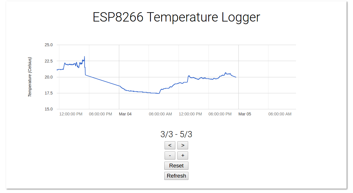
A common use for IoT devices like the ESP8266 is monitoring sensors. Using the code in the previous example, we can request the time, and save some sensor values to a file. If we run a server as well, we can show this data in a pretty graph in a webpage.
Temperature logger
Installing libraries
First, download the Dallas Temperature library by Miles Burton and the OneWire library by Jim Studt: Go to Sketch > Include Library ... > Manage Libraries and search for 'Dallas Temperature' and 'OneWire' (make sure you download the correct version).
Hardware
Libraries, constants and globals
#include <OneWire.h>
#include <DallasTemperature.h>
#include <ESP8266WiFi.h>
#include <ESP8266WiFiMulti.h>
#include <WiFiUdp.h>
#include <ArduinoOTA.h>
#include <ESP8266WebServer.h>
#include <ESP8266mDNS.h>
#include <FS.h>

#define ONE_HOUR 3600000UL

#define TEMP_SENSOR_PIN 5

OneWire oneWire(TEMP_SENSOR_PIN);        // Set up a OneWire instance to communicate with OneWire devices

DallasTemperature tempSensors(&oneWire); // Create an instance of the temperature sensor class

ESP8266WebServer server = ESP8266WebServer(80);       // create a web server on port 80

File fsUploadFile;                                    // a File variable to temporarily store the received file

ESP8266WiFiMulti wifiMulti;    // Create an instance of the ESP8266WiFiMulti class, called 'wifiMulti'

const char *OTAName = "ESP8266";         // A name and a password for the OTA service
const char *OTAPassword = "esp8266";

const char* mdnsName = "esp8266";        // Domain name for the mDNS responder

WiFiUDP UDP;                   // Create an instance of the WiFiUDP class to send and receive UDP messages

IPAddress timeServerIP;        // The time.nist.gov NTP server's IP address
const char* ntpServerName = "time.nist.gov";

const int NTP_PACKET_SIZE = 48;          // NTP time stamp is in the first 48 bytes of the message

byte packetBuffer[ NTP_PACKET_SIZE]; // A buffer to hold incoming and outgoing packetsSetup
void setup() {
  Serial.begin(115200);        // Start the Serial communication to send messages to the computer
  delay(10);
  Serial.println("\r\n");

  tempSensors.setWaitForConversion(false); // Don't block the program while the temperature sensor is reading
  tempSensors.begin();                     // Start the temperature sensor

  if (tempSensors.getDeviceCount() == 0) {
    Serial.printf("No DS18x20 temperature sensor found on pin %d. Rebooting.\r\n", TEMP_SENSOR_PIN);
    Serial.flush();
    ESP.reset();
  }

  startWiFi();                 // Start a Wi-Fi access point, and try to connect to some given access points. Then wait for either an AP or STA connection

  startOTA();                  // Start the OTA service

  startSPIFFS();               // Start the SPIFFS and list all contents

  startMDNS();                 // Start the mDNS responder

  startServer();               // Start a HTTP server with a file read handler and an upload handler

  startUDP();                  // Start listening for UDP messages to port 123

  WiFi.hostByName(ntpServerName, timeServerIP); // Get the IP address of the NTP server
  Serial.print("Time server IP:\t");
  Serial.println(timeServerIP);

  sendNTPpacket(timeServerIP);
}Getting the temperature from the sensor may take some time (up to 750ms). We don't want our loop to take longer than a couple of milliseconds, so we can't wait 750ms. If we did, the HTTP server etc. would start to misbehave.
The solution is to request the temperature first. The sensor will then start reading the analog temperature, and stores it in its memory. In the meantime, the loop just keeps on running, the server refreshes etc. After 750ms, we contact the sensor again, and read the temperature from its memory.
To tell the library that we don't want to wait for the analog to digital conversion of the sensor, we use setWaitForConversion.
Loop
const unsigned long intervalNTP = ONE_HOUR; // Update the time every hour
unsigned long prevNTP = 0;
unsigned long lastNTPResponse = millis();

const unsigned long intervalTemp = 60000;   // Do a temperature measurement every minute
unsigned long prevTemp = 0;
bool tmpRequested = false;
const unsigned long DS_delay = 750;         // Reading the temperature from the DS18x20 can take up to 750ms

uint32_t timeUNIX = 0;                      // The most recent timestamp received from the time server

void loop() {
  unsigned long currentMillis = millis();

  if (currentMillis - prevNTP > intervalNTP) { // Request the time from the time server every hour
    prevNTP = currentMillis;
    sendNTPpacket(timeServerIP);
  }

  uint32_t time = getTime();                   // Check if the time server has responded, if so, get the UNIX time
  if (time) {
    timeUNIX = time;
    Serial.print("NTP response:\t");
    Serial.println(timeUNIX);
    lastNTPResponse = millis();
  } else if ((millis() - lastNTPResponse) > 24UL * ONE_HOUR) {
    Serial.println("More than 24 hours since last NTP response. Rebooting.");
    Serial.flush();
    ESP.reset();
  }

  if (timeUNIX != 0) {
    if (currentMillis - prevTemp > intervalTemp) {  // Every minute, request the temperature
      tempSensors.requestTemperatures(); // Request the temperature from the sensor (it takes some time to read it)
      tmpRequested = true;
      prevTemp = currentMillis;
      Serial.println("Temperature requested");
    }
    if (currentMillis - prevTemp > DS_delay && tmpRequested) { // 750 ms after requesting the temperature
      uint32_t actualTime = timeUNIX + (currentMillis - lastNTPResponse) / 1000;
      // The actual time is the last NTP time plus the time that has elapsed since the last NTP response
      tmpRequested = false;
      float temp = tempSensors.getTempCByIndex(0); // Get the temperature from the sensor
      temp = round(temp * 100.0) / 100.0; // round temperature to 2 digits

      Serial.printf("Appending temperature to file: %lu,", actualTime);
      Serial.println(temp);
      File tempLog = SPIFFS.open("/temp.csv", "a"); // Write the time and the temperature to the csv file
      tempLog.print(actualTime);
      tempLog.print(',');
      tempLog.println(temp);
      tempLog.close();
    }
  } else {                                    // If we didn't receive an NTP response yet, send another request
    sendNTPpacket(timeServerIP);
    delay(500);
  }

  server.handleClient();                      // run the server
  ArduinoOTA.handle();                        // listen for OTA events
}- Every hour, the ESP requests the time from an NTP server. Then it constantly checks for a response, and updates the time if it gets an NTP response. If it hasn't received any responses for over 24 hours, there's something wrong, and the ESP resets itself.
- Every minute, the ESP requests the temperature from the DS18x20 sensor, and sets the 'tmpRequested' flag. The sensor will start the analog to digital conversion.
750ms after the request, when the conversion should be finished, the ESP reads the temperature from the sensor, and resets the flag (otherwise, it would keep on reading the same temperature over and over again). Then it writes the time and the temperature to a file in SPIFFS.
By saving it as a CSV file in the filesystem, we can easily download it to the client (using the web server that is running), and it's easy to parse with JavaScript.
Setup functions, server handlers and helper functions
HTML and JavaScript
Using the example
Connecting
..........

Connected to SSID
IP address:	192.168.1.2

OTA ready

SPIFFS started. Contents:
	FS File: /favicon-144x144.png, size: 2.81KB
	FS File: /temperatureGraph.js.gz, size: 1.17KB
	FS File: /temp.csv, size: 42.50KB
	FS File: /success.html.gz, size: 456B
	FS File: /edit.html.gz, size: 700B
	FS File: /main.css.gz, size: 349B
	FS File: /index.html.gz, size: 795B
	FS File: /manifest.json, size: 169B
	FS File: /favicon.ico.gz, size: 1.91KB

mDNS responder started: http://esp8266.local
HTTP server started.
Starting UDP
Local port:	123
Time server IP:	216.229.0.179
Sending NTP request
NTP response:	1488666586
Temperature requested
Appending temperature to file: 1488666627,20.00
Temperature requested
Appending temperature to file: 1488666687,19.94
Temperature requested
...
ESP8266 Network Time Protocol
There are many applications where you want to know the time. In a normal Arduino project, you would have to get a RTC module, set the right time, sacrifice some Arduino pins for communication ... And when the RTC battery runs out, you have to replace it.
On the ESP8266, all you need is an Internet connection: you can just ask a time server what time it is. To do this, the Network Time Protocol (NTP) is used.
In the previous examples (HTTP, WebSockets) we've only used TCP connections, but NTP is based on UDP. There are a couple of differences, but it's really easy to use, thanks to the great libraries that come with the ESP8266 Arduino Core.
The main difference between TCP and UDP is that TCP needs a connection to send messages: First a handshake is sent by the client, the server responds, and a connection is established, and the client can send its messages. After the client has received the response of the server, the connection is closed (except when using WebSockets). To send a new message, the client has to open a new connection to the server first. This introduces latency and overhead.
UDP doesn't use a connection, a client can just send a message to the server directly, and the server can just send a response message back to the client when it has finished processing. There is, however, no guarantee that the messages will arrive at their destination, and there's no way to know whether they arrived or not (without sending an acknowledgement, of course). This means that we can't halt the program to wait for a response, because the request or response packet could have been lost on the Internet, and the ESP8266 will enter an infinite loop.
Instead of waiting for a response, we just send multiple requests, with a fixed interval between two requests, and just regularly check if a response has been received.
Getting the time
Libraries, constants and globals
#include <ESP8266WiFi.h>
#include <ESP8266WiFiMulti.h>
#include <WiFiUdp.h>

ESP8266WiFiMulti wifiMulti;      // Create an instance of the ESP8266WiFiMulti class, called 'wifiMulti'

WiFiUDP UDP;                     // Create an instance of the WiFiUDP class to send and receive

IPAddress timeServerIP;          // time.nist.gov NTP server address
const char* NTPServerName = "time.nist.gov";

const int NTP_PACKET_SIZE = 48;  // NTP time stamp is in the first 48 bytes of the message

byte NTPBuffer[NTP_PACKET_SIZE]; // buffer to hold incoming and outgoing packetsSetup
void setup() {
  Serial.begin(115200);          // Start the Serial communication to send messages to the computer
  delay(10);
  Serial.println("\r\n");

  startWiFi();                   // Try to connect to some given access points. Then wait for a connection

  startUDP();

  if(!WiFi.hostByName(NTPServerName, timeServerIP)) { // Get the IP address of the NTP server
    Serial.println("DNS lookup failed. Rebooting.");
    Serial.flush();
    ESP.reset();
  }
  Serial.print("Time server IP:\t");
  Serial.println(timeServerIP);

  Serial.println("\r\nSending NTP request ...");
  sendNTPpacket(timeServerIP);
}Loop
unsigned long intervalNTP = 60000; // Request NTP time every minute
unsigned long prevNTP = 0;
unsigned long lastNTPResponse = millis();
uint32_t timeUNIX = 0;

unsigned long prevActualTime = 0;

void loop() {
  unsigned long currentMillis = millis();

  if (currentMillis - prevNTP > intervalNTP) { // If a minute has passed since last NTP request
    prevNTP = currentMillis;
    Serial.println("\r\nSending NTP request ...");
    sendNTPpacket(timeServerIP);               // Send an NTP request
  }

  uint32_t time = getTime();                   // Check if an NTP response has arrived and get the (UNIX) time
  if (time) {                                  // If a new timestamp has been received
    timeUNIX = time;
    Serial.print("NTP response:\t");
    Serial.println(timeUNIX);
    lastNTPResponse = currentMillis;
  } else if ((currentMillis - lastNTPResponse) > 3600000) {
    Serial.println("More than 1 hour since last NTP response. Rebooting.");
    Serial.flush();
    ESP.reset();
  }

  uint32_t actualTime = timeUNIX + (currentMillis - lastNTPResponse)/1000;
  if (actualTime != prevActualTime && timeUNIX != 0) { // If a second has passed since last print
    prevActualTime = actualTime;
    Serial.printf("\rUTC time:\t%d:%d:%d   ", getHours(actualTime), getMinutes(actualTime), getSeconds(actualTime));
  }
}Setup functions
void startWiFi() { // Try to connect to some given access points. Then wait for a connection
  wifiMulti.addAP("ssid_from_AP_1", "your_password_for_AP_1");   // add Wi-Fi networks you want to connect to
  wifiMulti.addAP("ssid_from_AP_2", "your_password_for_AP_2");
  wifiMulti.addAP("ssid_from_AP_3", "your_password_for_AP_3");

  Serial.println("Connecting");
  while (wifiMulti.run() != WL_CONNECTED) {  // Wait for the Wi-Fi to connect
    delay(250);
    Serial.print('.');
  }
  Serial.println("\r\n");
  Serial.print("Connected to ");
  Serial.println(WiFi.SSID());             // Tell us what network we're connected to
  Serial.print("IP address:\t");
  Serial.print(WiFi.localIP());            // Send the IP address of the ESP8266 to the computer
  Serial.println("\r\n");
}

void startUDP() {
  Serial.println("Starting UDP");
  UDP.begin(123);                          // Start listening for UDP messages on port 123
  Serial.print("Local port:\t");
  Serial.println(UDP.localPort());
  Serial.println();
}
Helper functions
uint32_t getTime() {
  if (UDP.parsePacket() == 0) { // If there's no response (yet)
    return 0;
  }
  UDP.read(NTPBuffer, NTP_PACKET_SIZE); // read the packet into the buffer
  // Combine the 4 timestamp bytes into one 32-bit number
  uint32_t NTPTime = (NTPBuffer[40] << 24) | (NTPBuffer[41] << 16) | (NTPBuffer[42] << 8) | NTPBuffer[43];
  // Convert NTP time to a UNIX timestamp:
  // Unix time starts on Jan 1 1970. That's 2208988800 seconds in NTP time:
  const uint32_t seventyYears = 2208988800UL;
  // subtract seventy years:
  uint32_t UNIXTime = NTPTime - seventyYears;
  return UNIXTime;
}

void sendNTPpacket(IPAddress& address) {
  memset(NTPBuffer, 0, NTP_PACKET_SIZE);  // set all bytes in the buffer to 0
  // Initialize values needed to form NTP request
  NTPBuffer[0] = 0b11100011;   // LI, Version, Mode
  // send a packet requesting a timestamp:
  UDP.beginPacket(address, 123); // NTP requests are to port 123
  UDP.write(NTPBuffer, NTP_PACKET_SIZE);
  UDP.endPacket();
}

inline int getSeconds(uint32_t UNIXTime) {
  return UNIXTime % 60;
}

inline int getMinutes(uint32_t UNIXTime) {
  return UNIXTime / 60 % 60;
}

inline int getHours(uint32_t UNIXTime) {
  return UNIXTime / 3600 % 24;
}Using the example
Connecting
.........

Connected to Wi-Fi SSID
IP address:	192.168.1.2

Starting UDP
Local port:	123

Time server IP:	216.229.0.179

Sending NTP request ...
NTP response:	1488378061
UTC time:	14:21:53
Sending NTP request ...
NTP response:	1488378114
UTC time:	14:22:53
Sending NTP request ...
NTP response:	1488378174
UTC time:	14:23:53
Sending NTP request ...
NTP response:	1488378234
UTC time:	14:24:53
Sending NTP request ...
NTP response:	1488378294
UTC time:	14:25:53
...Connecting
.........
Connected to Wi-Fi SSID
IP address: 192.168.1.2
Starting UDP
Local port: 123
DNS lookup failed. Rebooting.
ets Jan 8 2013,rst cause:2, boot mode:(3,6)Sending NTP request ...
NTP response: 1488378780
UTC time: 14:33:54
Sending NTP request ...
UTC time: 14:34:54
Sending NTP request ...
NTP response: 1488378895
UTC time: 14:35:0Local time and daylight savings
ESP8266 WebSocket communication
Controlling RGB LEDs from a web interface using WebSocket
Improving readability
In the following example, the setup was very long and cluttered, so I split it up into several different functions: one to connect to the Wi-Fi, one to start the OTA update service, one to start the SPIFFS ... and so on.
Downloading WebSockets for Arduino
Libraries, constants and globals
#include <ESP8266WiFi.h>
#include <ESP8266WiFiMulti.h>
#include <ArduinoOTA.h>
#include <ESP8266WebServer.h>
#include <ESP8266mDNS.h>
#include <FS.h>
#include <WebSocketsServer.h>

ESP8266WiFiMulti wifiMulti;       // Create an instance of the ESP8266WiFiMulti class, called 'wifiMulti'

ESP8266WebServer server = ESP8266WebServer(80);       // create a web server on port 80
WebSocketsServer webSocket = WebSocketsServer(81);    // create a websocket server on port 81

File fsUploadFile;                                    // a File variable to temporarily store the received file

const char *ssid = "ESP8266 Access Point"; // The name of the Wi-Fi network that will be created
const char *password = "thereisnospoon";   // The password required to connect to it, leave blank for an open network

const char *OTAName = "ESP8266";           // A name and a password for the OTA service
const char *OTAPassword = "esp8266";

#define LED_RED     15            // specify the pins with an RGB LED connected
#define LED_GREEN   12
#define LED_BLUE    13

const char* mdnsName = "esp8266"; // Domain name for the mDNS responderSetup
void setup() {
  pinMode(LED_RED, OUTPUT);    // the pins with LEDs connected are outputs
  pinMode(LED_GREEN, OUTPUT);
  pinMode(LED_BLUE, OUTPUT);

  Serial.begin(115200);        // Start the Serial communication to send messages to the computer
  delay(10);
  Serial.println("\r\n");

  startWiFi();                 // Start a Wi-Fi access point, and try to connect to some given access points. Then wait for either an AP or STA connection

  startOTA();                  // Start the OTA service

  startSPIFFS();               // Start the SPIFFS and list all contents

  startWebSocket();            // Start a WebSocket server

  startMDNS();                 // Start the mDNS responder

  startServer();               // Start a HTTP server with a file read handler and an upload handler

}Loop
bool rainbow = false;             // The rainbow effect is turned off on startup

unsigned long prevMillis = millis();
int hue = 0;

void loop() {
  webSocket.loop();                           // constantly check for websocket events
  server.handleClient();                      // run the server
  ArduinoOTA.handle();                        // listen for OTA events

  if(rainbow) {                               // if the rainbow effect is turned on
    if(millis() > prevMillis + 32) {
      if(++hue == 360)                        // Cycle through the color wheel (increment by one degree every 32 ms)
        hue = 0;
      setHue(hue);                            // Set the RGB LED to the right color
      prevMillis = millis();
    }
  }
}Setup functions
void startWiFi() { // Start a Wi-Fi access point, and try to connect to some given access points. Then wait for either an AP or STA connection
  WiFi.softAP(ssid, password);             // Start the access point
  Serial.print("Access Point \"");
  Serial.print(ssid);
  Serial.println("\" started\r\n");

  wifiMulti.addAP("ssid_from_AP_1", "your_password_for_AP_1");   // add Wi-Fi networks you want to connect to
  wifiMulti.addAP("ssid_from_AP_2", "your_password_for_AP_2");
  wifiMulti.addAP("ssid_from_AP_3", "your_password_for_AP_3");

  Serial.println("Connecting");
  while (wifiMulti.run() != WL_CONNECTED && WiFi.softAPgetStationNum() < 1) {  // Wait for the Wi-Fi to connect
    delay(250);
    Serial.print('.');
  }
  Serial.println("\r\n");
  if(WiFi.softAPgetStationNum() == 0) {      // If the ESP is connected to an AP
    Serial.print("Connected to ");
    Serial.println(WiFi.SSID());             // Tell us what network we're connected to
    Serial.print("IP address:\t");
    Serial.print(WiFi.localIP());            // Send the IP address of the ESP8266 to the computer
  } else {                                   // If a station is connected to the ESP SoftAP
    Serial.print("Station connected to ESP8266 AP");
  }
  Serial.println("\r\n");
}

void startOTA() { // Start the OTA service
  ArduinoOTA.setHostname(OTAName);
  ArduinoOTA.setPassword(OTAPassword);

  ArduinoOTA.onStart([]() {
    Serial.println("Start");
    digitalWrite(LED_RED, 0);    // turn off the LEDs
    digitalWrite(LED_GREEN, 0);
    digitalWrite(LED_BLUE, 0);
  });
  ArduinoOTA.onEnd([]() {
    Serial.println("\r\nEnd");
  });
  ArduinoOTA.onProgress([](unsigned int progress, unsigned int total) {
    Serial.printf("Progress: %u%%\r", (progress / (total / 100)));
  });
  ArduinoOTA.onError([](ota_error_t error) {
    Serial.printf("Error[%u]: ", error);
    if (error == OTA_AUTH_ERROR) Serial.println("Auth Failed");
    else if (error == OTA_BEGIN_ERROR) Serial.println("Begin Failed");
    else if (error == OTA_CONNECT_ERROR) Serial.println("Connect Failed");
    else if (error == OTA_RECEIVE_ERROR) Serial.println("Receive Failed");
    else if (error == OTA_END_ERROR) Serial.println("End Failed");
  });
  ArduinoOTA.begin();
  Serial.println("OTA ready\r\n");
}

void startSPIFFS() { // Start the SPIFFS and list all contents
  SPIFFS.begin();                             // Start the SPI Flash File System (SPIFFS)
  Serial.println("SPIFFS started. Contents:");
  {
    Dir dir = SPIFFS.openDir("/");
    while (dir.next()) {                      // List the file system contents
      String fileName = dir.fileName();
      size_t fileSize = dir.fileSize();
      Serial.printf("\tFS File: %s, size: %s\r\n", fileName.c_str(), formatBytes(fileSize).c_str());
    }
    Serial.printf("\n");
  }
}

void startWebSocket() { // Start a WebSocket server
  webSocket.begin();                          // start the websocket server
  webSocket.onEvent(webSocketEvent);          // if there's an incomming websocket message, go to function 'webSocketEvent'
  Serial.println("WebSocket server started.");
}

void startMDNS() { // Start the mDNS responder
  MDNS.begin(mdnsName);                        // start the multicast domain name server
  Serial.print("mDNS responder started: http://");
  Serial.print(mdnsName);
  Serial.println(".local");
}

void startServer() { // Start a HTTP server with a file read handler and an upload handler
  server.on("/edit.html",  HTTP_POST, []() {  // If a POST request is sent to the /edit.html address,
    server.send(200, "text/plain", "");
  }, handleFileUpload);                       // go to 'handleFileUpload'

  server.onNotFound(handleNotFound);          // if someone requests any other file or page, go to function 'handleNotFound'
                                              // and check if the file exists

  server.begin();                             // start the HTTP server
  Serial.println("HTTP server started.");
}Server handlers
void handleNotFound(){ // if the requested file or page doesn't exist, return a 404 not found error
  if(!handleFileRead(server.uri())){          // check if the file exists in the flash memory (SPIFFS), if so, send it
    server.send(404, "text/plain", "404: File Not Found");
  }
}

bool handleFileRead(String path) { // send the right file to the client (if it exists)
  Serial.println("handleFileRead: " + path);
  if (path.endsWith("/")) path += "index.html";          // If a folder is requested, send the index file
  String contentType = getContentType(path);             // Get the MIME type
  String pathWithGz = path + ".gz";
  if (SPIFFS.exists(pathWithGz) || SPIFFS.exists(path)) { // If the file exists, either as a compressed archive, or normal
    if (SPIFFS.exists(pathWithGz))                         // If there's a compressed version available
      path += ".gz";                                         // Use the compressed verion
    File file = SPIFFS.open(path, "r");                    // Open the file
    size_t sent = server.streamFile(file, contentType);    // Send it to the client
    file.close();                                          // Close the file again
    Serial.println(String("\tSent file: ") + path);
    return true;
  }
  Serial.println(String("\tFile Not Found: ") + path);   // If the file doesn't exist, return false
  return false;
}

void handleFileUpload(){ // upload a new file to the SPIFFS
  HTTPUpload& upload = server.upload();
  String path;
  if(upload.status == UPLOAD_FILE_START){
    path = upload.filename;
    if(!path.startsWith("/")) path = "/"+path;
    if(!path.endsWith(".gz")) {                          // The file server always prefers a compressed version of a file
      String pathWithGz = path+".gz";                    // So if an uploaded file is not compressed, the existing compressed
      if(SPIFFS.exists(pathWithGz))                      // version of that file must be deleted (if it exists)
         SPIFFS.remove(pathWithGz);
    }
    Serial.print("handleFileUpload Name: "); Serial.println(path);
    fsUploadFile = SPIFFS.open(path, "w");            // Open the file for writing in SPIFFS (create if it doesn't exist)
    path = String();
  } else if(upload.status == UPLOAD_FILE_WRITE){
    if(fsUploadFile)
      fsUploadFile.write(upload.buf, upload.currentSize); // Write the received bytes to the file
  } else if(upload.status == UPLOAD_FILE_END){
    if(fsUploadFile) {                                    // If the file was successfully created
      fsUploadFile.close();                               // Close the file again
      Serial.print("handleFileUpload Size: "); Serial.println(upload.totalSize);
      server.sendHeader("Location","/success.html");      // Redirect the client to the success page
      server.send(303);
    } else {
      server.send(500, "text/plain", "500: couldn't create file");
    }
  }
}

void webSocketEvent(uint8_t num, WStype_t type, uint8_t * payload, size_t lenght) { // When a WebSocket message is received
  switch (type) {
    case WStype_DISCONNECTED:             // if the websocket is disconnected
      Serial.printf("[%u] Disconnected!\n", num);
      break;
    case WStype_CONNECTED: {              // if a new websocket connection is established
        IPAddress ip = webSocket.remoteIP(num);
        Serial.printf("[%u] Connected from %d.%d.%d.%d url: %s\n", num, ip[0], ip[1], ip[2], ip[3], payload);
        rainbow = false;                  // Turn rainbow off when a new connection is established
      }
      break;
    case WStype_TEXT:                     // if new text data is received
      Serial.printf("[%u] get Text: %s\n", num, payload);
      if (payload[0] == '#') {            // we get RGB data
        uint32_t rgb = (uint32_t) strtol((const char *) &payload[1], NULL, 16);   // decode rgb data
        int r = ((rgb >> 20) & 0x3FF);                     // 10 bits per color, so R: bits 20-29
        int g = ((rgb >> 10) & 0x3FF);                     // G: bits 10-19
        int b =          rgb & 0x3FF;                      // B: bits  0-9

        analogWrite(LED_RED,   r);                         // write it to the LED output pins
        analogWrite(LED_GREEN, g);
        analogWrite(LED_BLUE,  b);
      } else if (payload[0] == 'R') {                      // the browser sends an R when the rainbow effect is enabled
        rainbow = true;
      } else if (payload[0] == 'N') {                      // the browser sends an N when the rainbow effect is disabled
        rainbow = false;
      }
      break;
  }
}HTML
<!DOCTYPE html>
<html>
<head>
<title>LED Control</title>
<link href='https://fonts.googleapis.com/css?family=Roboto:300' rel='stylesheet' type='text/css'>
<link href='main.css' rel='stylesheet' type='text/css'>
<link rel="apple-touch-icon" sizes="180x180" href="/apple-touch-icon-180x180.png">
<link rel="icon" type="image/png" sizes="144x144" href="/favicon-144x144.png">
<link rel="icon" type="image/png" sizes="48x48" href="/favicon.ico">
<link rel="manifest" href="/manifest.json">
<meta name="theme-color" content="#00878f">
<meta content='width=device-width, initial-scale=1.0, maximum-scale=1.0, user-scalable=0' name='viewport'>
<script src="/WebSocket.js" type="text/javascript"></script>
</head>
<body>
<center>
<header>
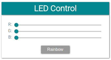
<h1>LED Control</h1>
</header>
<div>
<table>
<tr>
<td style="width:14.4px; text-align: right">R: </td>
<td><input class="enabled" id="r" type="range" min="0" max="1023" step="1" oninput="sendRGB();" value="0"></td>
</tr>
<tr>
<td style="width:14.4px; text-align: right">G: </td>
<td><input class="enabled" id="g" type="range" min="0" max="1023" step="1" oninput="sendRGB();" value="0"></td>
</tr>
<tr>
<td style="width:14.4px; text-align: right">B: </td>
<td><input class="enabled" id="b" type="range" min="0" max="1023" step="1" oninput="sendRGB();" value="0"></td>
</tr>
</table>
<p style="margin:8px 0px">
<button id="rainbow" class="button" style="background-color:#999" onclick="rainbowEffect();">Rainbow</button>
</p>
</div>
</center>
</body>
</html>There's really not much to it, just 3 sliders and a button linked to JavaScript functions.
JavaScript
var rainbowEnable = false;
var connection = new WebSocket('ws://' + location.hostname + ':81/', ['arduino']);
connection.onopen = function () {
  connection.send('Connect ' + new Date());
};
connection.onerror = function (error) {
  console.log('WebSocket Error ', error);
};
connection.onmessage = function (e) {
  console.log('Server: ', e.data);
};
connection.onclose = function () {
  console.log('WebSocket connection closed');
};

function sendRGB () {
  var r = document.getElementById('r').value** 2 / 1023;
  var g = document.getElementById('g').value** 2 / 1023;
  var b = document.getElementById('b').value** 2 / 1023;

  var rgb = r << 20 | g << 10 | b;
  var rgbstr = '#' + rgb.toString(16);
  console.log('RGB: ' + rgbstr);
  connection.send(rgbstr);
}

function rainbowEffect () {
  rainbowEnable = ! rainbowEnable;
  if (rainbowEnable) {
    connection.send("R");
    document.getElementById('rainbow').style.backgroundColor = '#00878F';
    document.getElementById('r').className = 'disabled';
    document.getElementById('g').className = 'disabled';
    document.getElementById('b').className = 'disabled';
    document.getElementById('r').disabled = true;
    document.getElementById('g').disabled = true;
    document.getElementById('b').disabled = true;
  } else {
    connection.send("N");
    document.getElementById('rainbow').style.backgroundColor = '#999';
    document.getElementById('r').className = 'enabled';
    document.getElementById('g').className = 'enabled';
    document.getElementById('b').className = 'enabled';
    document.getElementById('r').disabled = false;
    document.getElementById('g').disabled = false;
    document.getElementById('b').disabled = false;
    sendRGB();
  }
}Helper functions
String formatBytes(size_t bytes) { // convert sizes in bytes to KB and MB
  if (bytes < 1024) {
    return String(bytes) + "B";
  } else if (bytes < (1024 * 1024)) {
    return String(bytes / 1024.0) + "KB";
  } else if (bytes < (1024 * 1024 * 1024)) {
    return String(bytes / 1024.0 / 1024.0) + "MB";
  }
}

String getContentType(String filename) { // determine the filetype of a given filename, based on the extension
  if (filename.endsWith(".html")) return "text/html";
  else if (filename.endsWith(".css")) return "text/css";
  else if (filename.endsWith(".js")) return "application/javascript";
  else if (filename.endsWith(".ico")) return "image/x-icon";
  else if (filename.endsWith(".gz")) return "application/x-gzip";
  return "text/plain";
}

void setHue(int hue) { // Set the RGB LED to a given hue (color) (0° = Red, 120° = Green, 240° = Blue)
  hue %= 360;                   // hue is an angle between 0 and 359°
  float radH = hue*3.142/180;   // Convert degrees to radians
  float rf, gf, bf;

  if(hue>=0 && hue<120){        // Convert from HSI color space to RGB
    rf = cos(radH*3/4);
    gf = sin(radH*3/4);
    bf = 0;
  } else if(hue>=120 && hue<240){
    radH -= 2.09439;
    gf = cos(radH*3/4);
    bf = sin(radH*3/4);
    rf = 0;
  } else if(hue>=240 && hue<360){
    radH -= 4.188787;
    bf = cos(radH*3/4);
    rf = sin(radH*3/4);
    gf = 0;
  }
  int r = rf*rf*1023;
  int g = gf*gf*1023;
  int b = bf*bf*1023;

  analogWrite(LED_RED,   r);    // Write the right color to the LED output pins
  analogWrite(LED_GREEN, g);
  analogWrite(LED_BLUE,  b);
}
Using the example