ESP8266 – Developer board for the ESP-01 and ESP-12
Not sure what might be the expression in English to express my level of frustration, but I finally gave up on Lua and the Nodemcu firmware for the ESP8266. The combo of ESPlorer and Nodemcu with the fact that isn’t required to flash the ESP8266 to deploy and test new code is in fact a great advantage. But this comes with a price, a hefty price. Above certain levels of complexity or code size, the Nodemcu firmware just starts to reboot randomly or hangs, and this adds a high level of frustration to developing medium size program. Add one more instruction, or line, and presto. It doesn’t work anymore, and I’m starting to delete comments, spaces, empty lines, to make it work again… Why bother… I’m not alone on this one:4 reasons for leaving nodemcu…. My opinion Nodemcu is great for simple things and fine for testing, even if there is the need to learn Lua. Anything above that, there are better alternatives now and on the horizon.
Solving the problem
The problem that Nodemcu solves is the fact that we don’t need to flash any new firmware to test new programs or code. To flash new firmware we need to pull GPIO0 to Ground and pulse reset and then use a program, like esptool.py to push the new firmware to the chip. With Nodemcu we do this only once, on the initial ESP8266 configuration.
For other alternative firmwares, we need to always flash the firmware with the new code/program.
But the esptool.py holds a secret, it can pulse the physical serial port lines DTR and RTS to command GPIO0 and RESET to initiate the ESP8266 in flash mode, transfer the firmware, and when it ends releases the lines and allows the ESP8266 to run the new code. All without changing any connections on the ESP8266 at the physical level. In fact with this we can have the same functionality as the Nodemcu witth other firmwares. Off course off the shelf (ebay…) chips don’t do that, but I’m aware that Nodemcu and Olimex boards do support this kind of flashing mode control through the serial port. I could just bought one of these, but after programming the ESP8266 remains attached to that support electronics (serial chip) that might not be needed anymore.
So off we go building a developer board that allows the easy flashing and programming the ESP8266 but then allows the chip, namely ESP-01 and ESP-12 to detach and be used on their final board.
The board
My idealized board and in semi state of final construction (proto board) supports the esptool.py firmware flashing, powers up either from a power supply or trough mini-usb, and can program the ESP-01 or ESP-12.
My design is based on a circuit available in the esp8266.ru site, with some modifications. Also, due to the fact the DTR and RTS lines do have a function now, it’s necessary that the serial terminal programs do control these lines correctly to see, if desired, the serial port output. The serial console of ESPlorer works just fine and it has specific buttons to control these lines. In fact by pressing the RTS line button we can reset by hardware the ESP8266…
All components of the board are sourced from available items on ebay, which means that building the board is just to solder and connect some components on a protoboard with connector headers for the ESP-01 and ESP-12. Also the board can program both types, but only one at the time…
The USB serial adapter
The USB serial adapter must be one that exposes the RTS and DTR lines, and provides the serial lines at 3.3V, the level for the ESP8266. There are CP2102 based boards available on ebay or DX, that expose all the lines and are 3.3v level.
I bought mine from Alice1101983 on ebay:
It’s data and control pins are 3.3v level, just right for the ESP8266, so no need to do any level conversion, and exposes the DTR and RTS pins. Notice the board holes on the side that have the other exposed pins: (Image from Alixpress).
We need to solder a wire from the RTS pin to the ESP8266 RESET pin.
Power source
I’m not powering up the board through the USB/serial adapter. The serial port adapter does have a 3.3v power pin and also a 5v power pin. But the ESP8266 can demand high currents and the 3.3v regulator on the USB/serial adapter is almost certain not to be able to provide that current, even knowing that the USB port can provide 0.5A.
So I’m not using the power provided by the CP2102 serial adapter, and instead I’m using an MB102 bread board power supply with mini usb connector that can provide 5V and 3.3v outputs. I’ve also bought mine on alice1101983: 
This specific board receives power through the usual DC jack, but with the mini-usb connector it also can receive power from an USB power supply (mobile charger), or, even better, an USB power bank.
One of the MB102 board outputs is set to 3.3v to power up the ESP8266 boards and any other 3.3v devices, and the other other power output is set to 5V and connected to an IIC I2C level converter allowing the use of I2C 5V level devices like the 16×02 LCD screens.
I’m using these level converter devices: 
Schematics
The schematics that I’m using are based on this schematics:

I’ve got this from the ESP8266.RU site, the same from ESPlorer, and done some modifications.
With this schema, I can use the Arduino IDE and esptool.py to program the ESP8266 without the need of explicitly enter the firmware flash mode.
Also I’m not showing in my schematics the ESP-12 connections, but they are in parallel for the RX, TX, RTS and DTR lines.
A word of caution
Since now the RTS and DTR lines do have a function, some serial programs to access the ESP8266 serial console do not work. ESPlorer terminal works fine, and it has a handy DTR and RTS toggle buttons.
I’m using my own brewed python pyserial based serial program, that correctly set the RTS and DTR lines, so that after flashing the firmware we can see the serial output if any.
Also the way that reset switch resistor is in series with the switch AFTER the reset pin, means that with the serial port adapter is connected, the reset switch doesn’t work. Without being connected to the USB port, the reset switch works fine. The resistor is there to protect the CP2102 RTS line.
Final thoughts
I’m still waiting for the female headers to connect and start programming the ESP-12 on this developing board.
But so far, every thing is good. I’ve already tested the Arduino firmware ESP8266 Arduino Firmware, Sming, and off I go for testing https://github.com/cesanta/smart.js/tree/master and Espruino, which is a Javascript interpreter for the ESP8266.
ESP8266 Thing Hookup Guide
Installing the ESP8266 Arduino Addon
There are a variety of development environments that can be equipped to program the ESP8266. You can go with a simple Notepad/gcc setup, or fine-tune an Eclipse environment, use a virtual machine provided by Espressif, or come up with something of your own.
Fortunately, the amazing ESP8266 community recently took the IDE selection a step further by creating an Arduino addon. If you’re just getting started programming the ESP8266, this is the environment we recommend beginning with, and the one we’ll document in this tutorial.
This ESP8266 addon for Arduino is based on the amazing work by Ivan Grokhotkov and the rest of the ESP8266 community. Check out the ESP8266 Arduino GitHub repository for more information.
Installing the Addon With the Arduino Boards Manager
With the release of Arduino 1.6.4, adding third party boards to the Arduino IDE is easily achieved through the new board manager. If you’re running an older version of Arduino (1.6.3 or earlier), we recommend upgrading now. As always, you can download the latest version of Arduino from arduino.cc.
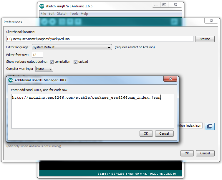
To begin, we’ll need to update the board manager with a custom URL. Open up Arduino, then go to the Preferences (File > Preferences). Then, towards the bottom of the window, copy this URL into the “Additional Board Manager URLs” text box:
http://arduino.esp8266.com/stable/package_esp8266com_index.json
If you already have a URL in there, and want to keep it, you can separate multiple URLs by placing a comma between them. (Arduino 1.6.5 added an expanded text box, separate links in here by line.)
Hit OK. Then navigate to the Board Manager by going to Tools > Boards > Boards Manager. There should be a couple new entries in addition to the standard Arduino boards. Look for esp8266. Click on that entry, then selectInstall.
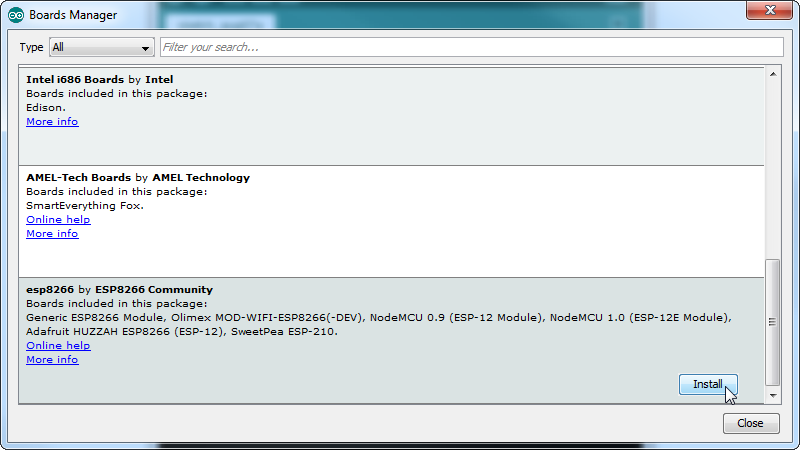
The board definitions and tools for the ESP8266 Thing include a whole new set of gcc, g++, and other reasonably large, compiled binaries, so it may take a few minutes to download and install (the archived file is ~110MB). Once the installation has completed, an Arduino-blue “INSTALLED” will appear next to the entry.
Selecting the ESP8266 Thing Board
With the Board addon installed, all that’s left to do is select “ESP8266 Thing” from the Tools > Boards menu.
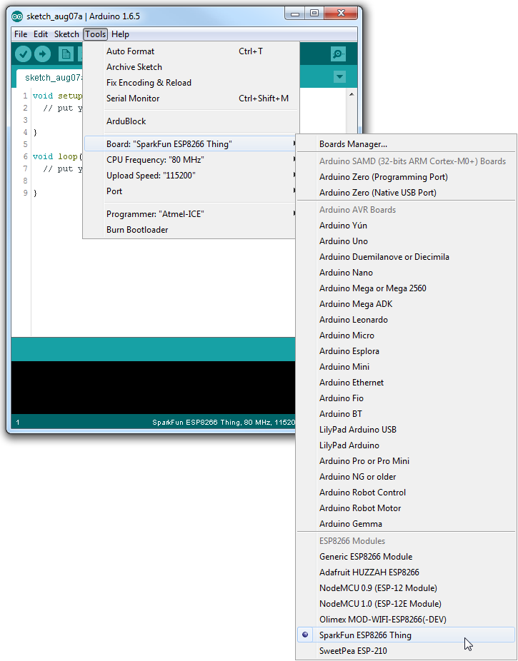
Then select your FTDI’s port number under the Tools > Port menu.
Upload Blink
To verify that everything works, try uploading the old standard: Blink. Instead of blinking pin 13, like you may be used to though, toggle pin 5, which is attached to the onboard LED.
#define ESP8266_LED 5

void setup()
{
  pinMode(ESP8266_LED, OUTPUT);
}

void loop()
{
  digitalWrite(ESP8266_LED, HIGH);
  delay(500);
  digitalWrite(ESP8266_LED, LOW);
  delay(500);
}
If the upload fails, first make sure the ESP8266 Thing is turned on – the red “PWR” LED should be illuminated.
Faster Uploads! The serial upload speed defaults to 115200 bps, which is reliable, but can feel a bit slow. You can increase the upload speed by a factor of about 8 by selecting 921600 under the Tools > Upload Speedmenu.
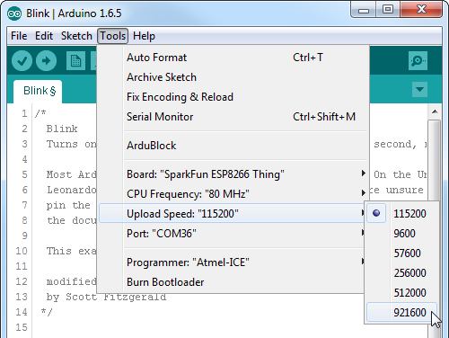
This faster upload speed can be slightly less reliable, but will save you loads of time!
There are still some bugs to be fleshed out of the esptool, sometimes it may take a couple tries to successfully upload a sketch. If you continue to fail, try turning the ESP8266 Thing on then off, or unplug then replug the FTDI in. If you still have trouble, get in touch with our amazing tech support team.
IP scores
IP scores: Hoe waterdicht is waterdicht?
Het eerste nummer verwijst naar de geboden bescherming tegen het binnendringen van objecten, zoals vingers of stof. Dit is een schaal die loopt van 0 tot 6.
Het tweede getal verwijst naar de geboden bescherming tegen het binnendringen van vocht, variërend van 0 tot 8. Wat ook wel eens voorkomt is een IP code met een 'X' in plaats van het eerste of tweede getal. Dit houdt in dat het apparaat op dat gebied niet is getest. In de volgende tabellen vindt je de geboden bescherming per categorie: